

Motor and Recording Disk Drive Device Provided with the Same
a technology of recording disk and motor, which is applied in the direction of dynamo-electric machines, electrical apparatus, magnetic circuit shapes/forms/construction, etc., can solve the problems of enlarging bearing losses, and achieve the effect of reducing the combined cogging waveform and being easy to adjus
- Summary
- Abstract
- Description
- Claims
- Application Information
AI Technical Summary
Benefits of technology
Problems solved by technology
Method used
Image

Examples
first preferred embodiment
[0037] 1-1 Configurations of Hard Disk Drive and Spindle Motor
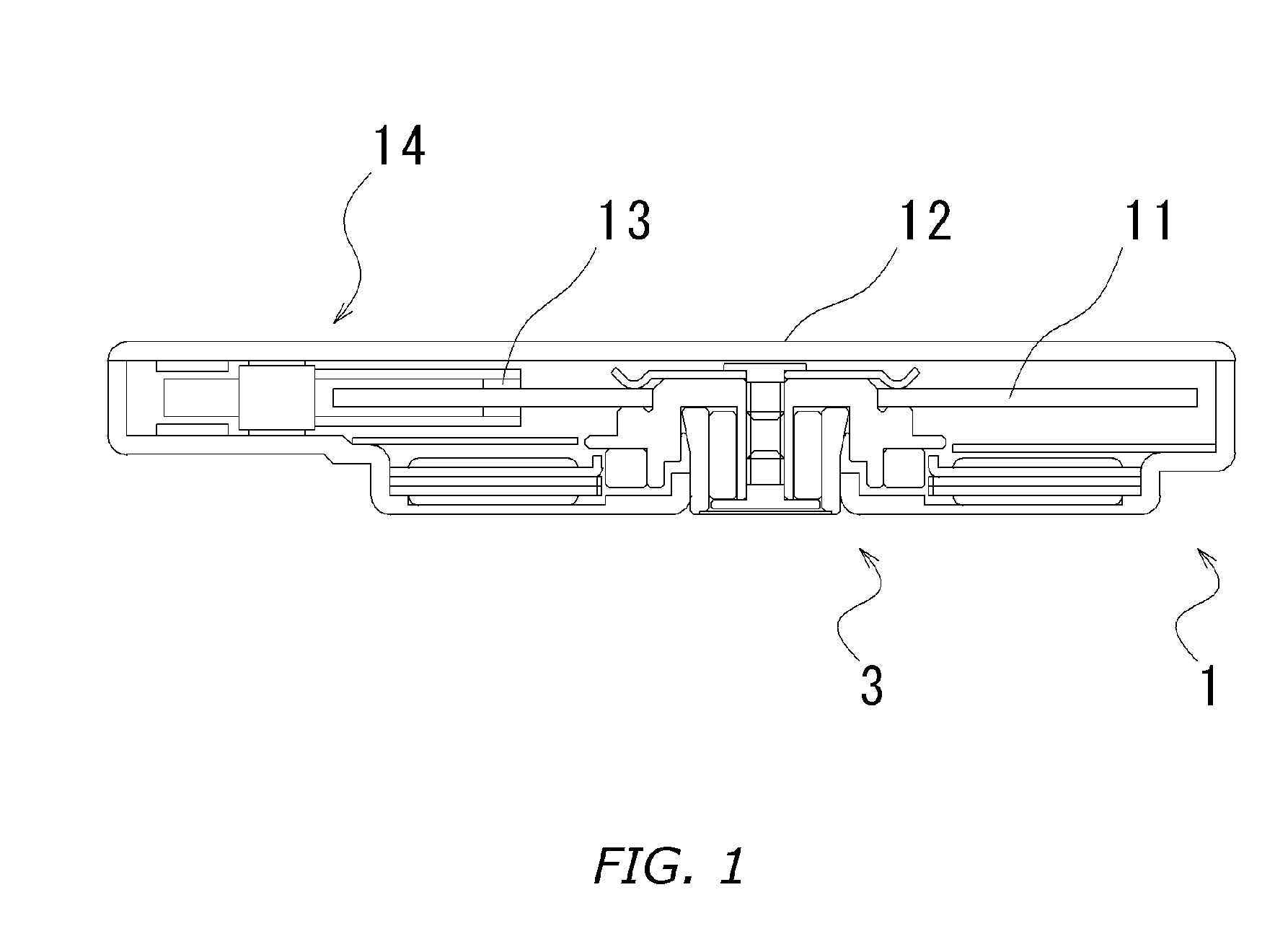
[0038]FIG. 1 shows a hard disk drive 1 according to the present invention, which is configured by using a spindle motor, which embodies the present invention. The hard disk drive 1 configured by using a spindle motor 3 according to the present invention contains, in a casing 12, an information recordable hard disk 11, a head 13, which reads or writes information stored in the disk, and a head assembly 14, which supports the head 13 and moves it to an arbitrary position on the disk.
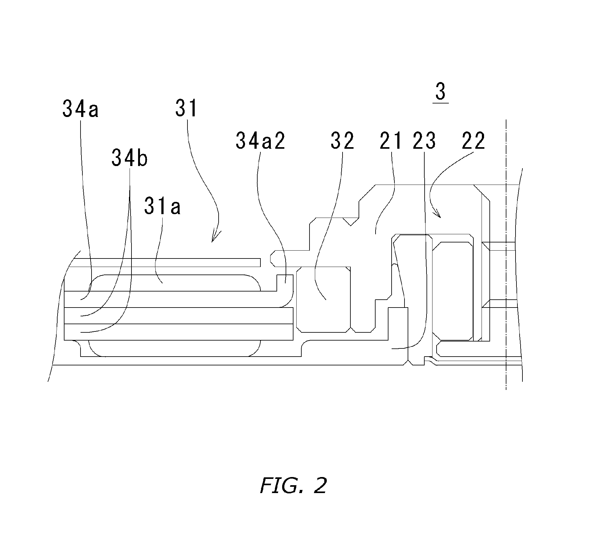
[0039] Furthermore, FIG. 2 shows the spindle motor 3 in a first preferred embodiment according to the present invention. The spindle motor 3 includes a rotor hub 21 provided with a mounting surface, on which the hard disk 11 is mounted, a base plate 23 serving as a part of the casing 12 and a base portion of the spindle motor 3, and a bearing 22 for rotatably supporting the rotor hub 21 with respect to the base plate 23.
[0040] The bearing 22 ...
second preferred embodiment
[0057] A spindle motor in a second preferred embodiment is different from that in the first preferred embodiment in the shape of the core 33. Therefore, a description will be given of only features different from those in the first preferred embodiment.
[0058] Here, members having the same functions or effects in the description in the present preferred embodiment are designated by the same reference numerals as those used in the first preferred embodiment even unless they have similar shapes.
[0059] 2-1 Shape of Core
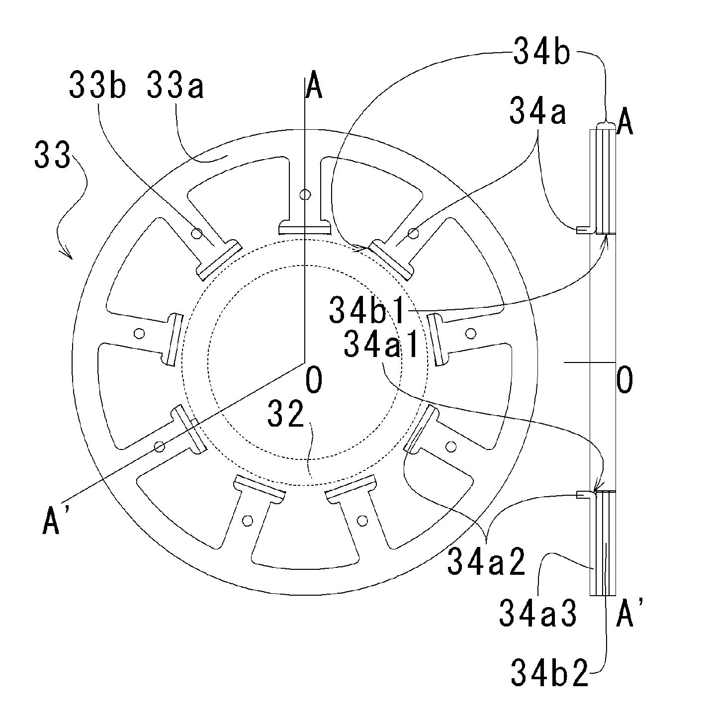
[0060]FIGS. 3C and 3D are a plan view and a perspective view showing the core 33 for use in a spindle motor 3 in the second preferred embodiment, respectively, as viewed from top in FIG. 2.
[0061] The core 33 includes a second core and a first core. A bent second core 34b is laminated on an uppermost side. Moreover, a first core 34a constituted of a plurality of flat core plates is laminated under the second core 34b.
[0062] The second core 34b has a bending portion 34...
third preferred embodiment
[0070] A spindle motor in a third preferred embodiment is different from the spindle motor 3 in the first preferred embodiment in the shape of the core. Therefore, a description will be given of only features different from those in the first preferred embodiment.
[0071] Here, members having the same functions or effects in the description in the present preferred embodiment are designated by the same reference numerals as those used in the first preferred embodiment even unless they have similar shapes.
[0072] 3-1 Shape of Core
[0073]FIGS. 7A and 7B are a plan view and a perspective view showing a core 33 for use in a spindle motor 3 in the third preferred embodiment, respectively, as viewed from top in FIG. 2.
[0074] A core 33 includes an annular core back 33a positioned on an outer peripheral side and magnetic pole teeth 33b extending inward in a radial direction from the core back 33a. The core 33 is constituted of a plurality of core plates 34, out of which a bent core plate is...
PUM
 Abstract
Description
Claims
Application Information