Film forming apparatus and method of driving same, device manufacturing method, device manufacturing apparatus, and device
a technology of film forming and film, which is applied in the direction of coating, instruments, printing, etc., can solve the problems of difficult discharge of high viscosity ink, inability to employ heat-lowering methods, and inability to improve the conditions of difficult discharge, so as to achieve high quality
- Summary
- Abstract
- Description
- Claims
- Application Information
AI Technical Summary
Benefits of technology
Problems solved by technology
Method used
Image
Examples
first embodiment
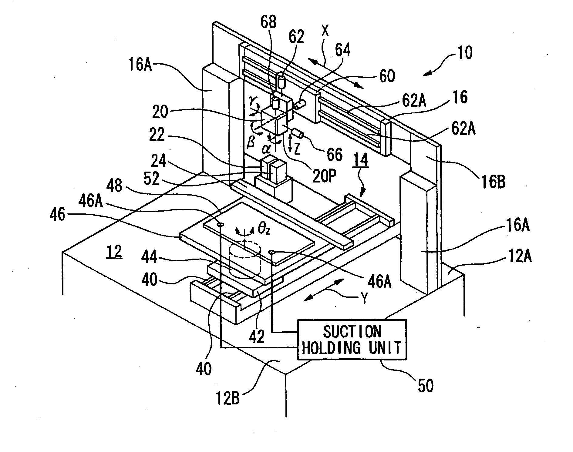
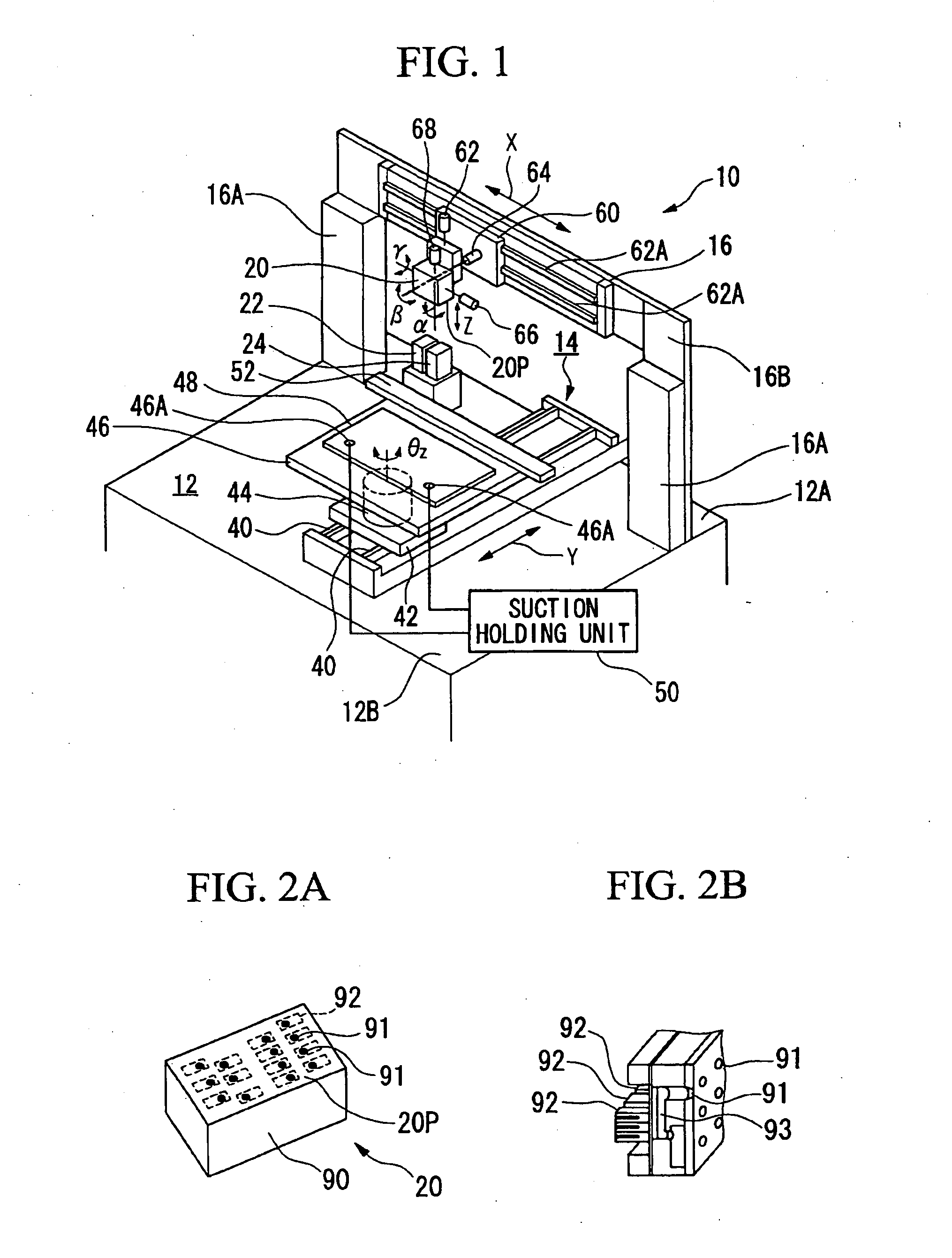
[0052] Embodiments of the film forming apparatus and method for driving the film forming apparatus, and the device manufacturing method, device manufacturing apparatus, and device of the present invention will now be described with reference to FIGS. 1 to 9.
[0053] Here, a description is given of an example of when the film forming apparatus of the present invention is used for a filter manufacturing apparatus that manufactures color filters and the like employed in liquid crystal devices using ink in the form of a liquid. Note that liquids that can be used in the present invention are included in the term liquid. Namely, in addition to the aforementioned liquids, the term “liquid” also refers to liquid bodies that contain, for example, minute particles such as metals or the like.
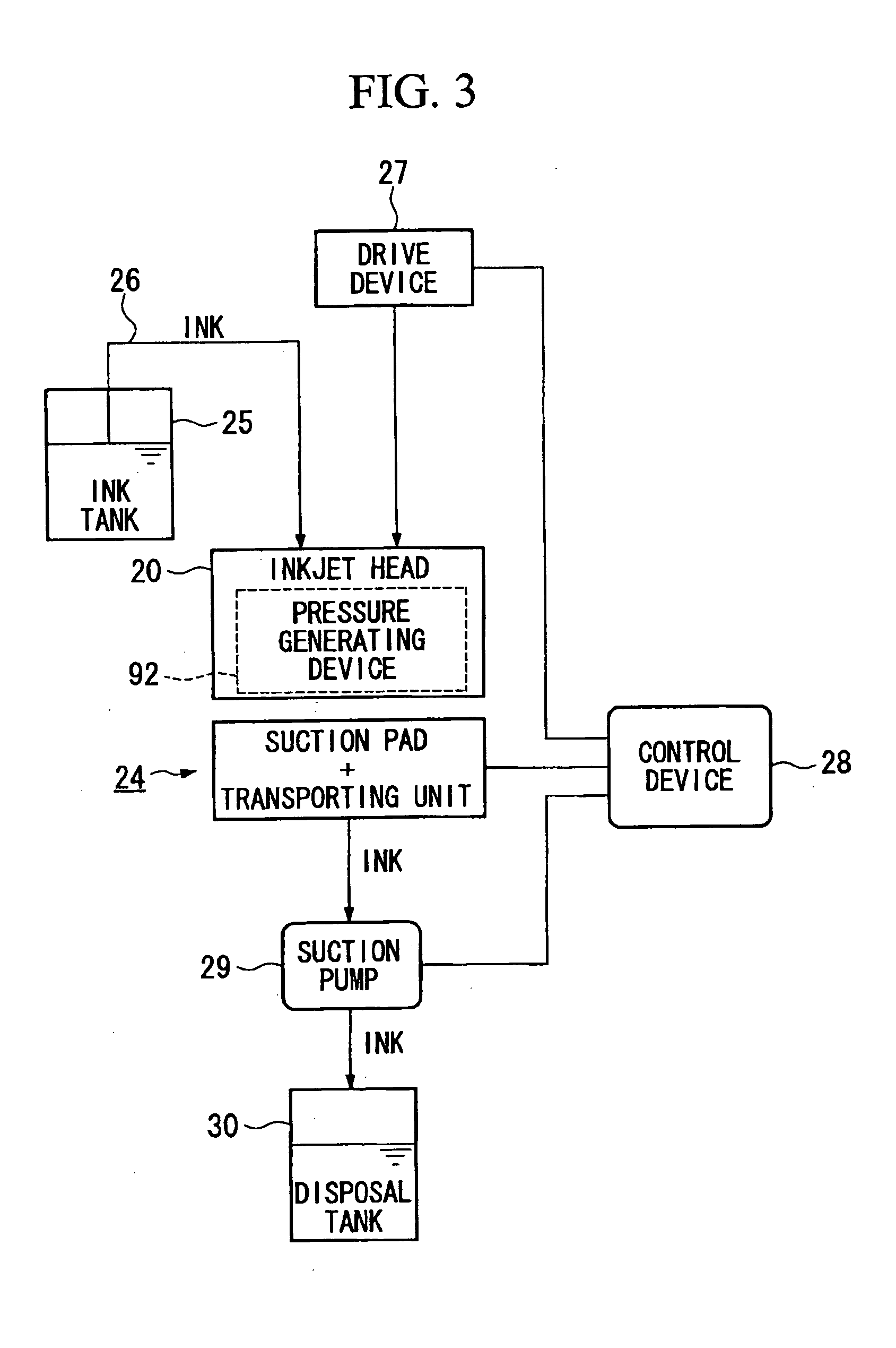
[0054]FIG. 1 is an external perspective view schematically showing a film forming apparatus (an inkjet apparatus) 10 that forms a filter manufacturing apparatus (i.e., a device manufacturing apparatus). Th...
second embodiment
[0098] As the second embodiment of the present invention, a description is given of when the film forming apparatus of the first embodiment is used as a manufacturing apparatus of an electro luminescence (EL) display device, with reference made to FIGS. 10 to 19.
[0099] An EL display device is an element having a structure in which a thin film containing fluorescent inorganic and organic compounds is sandwiched between a cathode and an anode. Electrons and holes are injected into this thin film and recombined thereby generating excitons. Light is generated by using the light (fluorescence and phosphorescence) emitted when the excitons are deactivated. Among fluorescent materials that are used for these EL display elements, materials that present luminescent colors of each of red, green, and blue, namely, luminescent layer forming materials and materials forming hole injection / electron transporting layers are used as inks, and by patterning each one on an element substrate such as a ...
third embodiment
[0150] As the third embodiment of the present invention, a description of when the film forming apparatus of the first embodiment is used as a manufacturing apparatus for a plasma display device (referred to below simply as the display device 325) will now be given.
[0151]FIG. 20 is an exploded perspective view of principal portions of a plasma display device.
[0152] In FIG. 20, the display device 325 is shown with a portion thereof cut away.
[0153] This display device 325 is schematically formed so as to include a first substrate 326 and a second substrate 327 that are placed facing each other, and by a discharge display section 328 formed between the two substrates. The discharge display section 328 is formed by a plurality of discharge chambers 329. Three discharge chambers 329, namely, a red discharge chamber 329 (R), a green discharge chamber 329 (G), and a blue discharge chamber 329 (B), from among the plurality of discharge chambers 329 form one group and are arranged so as t...
PUM
| Property | Measurement | Unit |
|---|---|---|
| temperature | aaaaa | aaaaa |
| thickness | aaaaa | aaaaa |
| length | aaaaa | aaaaa |
Abstract
Description
Claims
Application Information
 - R&D
- Intellectual Property
- Life Sciences
- Materials
- Tech Scout
- Unparalleled Data Quality
- Higher Quality Content
- 60% Fewer Hallucinations
Browse by: Latest US Patents, China's latest patents, Technical Efficacy Thesaurus, Application Domain, Technology Topic, Popular Technical Reports.
© 2025 PatSnap. All rights reserved.Legal|Privacy policy|Modern Slavery Act Transparency Statement|Sitemap|About US| Contact US: help@patsnap.com


