Supercontinuum emitting device

a light-emitting device and super-continuum technology, applied in the direction of cladding optical fibre, manufacturing tools, instruments, etc., can solve the problems of reducing the efficiency of four wave mixing, relying on very high peak pulse power, and generally not operating with typical cw light sources

Inactive Publication Date: 2006-09-07
CORNING INC
View PDF4 Cites 25 Cited by
  • Summary
  • Abstract
  • Description
  • Claims
  • Application Information

AI Technical Summary

Benefits of technology

[0027] (i) generating an effectively CW light of wavelength λ1 situated within a specified spectral bandwidth; and
[0028] (ii) optically coupling said e...

Problems solved by technology

One of the drawbacks of the method disclosed in U.S. Pat. No. 6,775,447 is that it relies on very high peak pulse power (on the order of 10 KW or larger) to produce the supercontinuum.
Therefore, this technique generally would not operate...

Method used


Image

  • Supercontinuum emitting device
  • Supercontinuum emitting device
  • Supercontinuum emitting device

Examples


Embodiment Construction

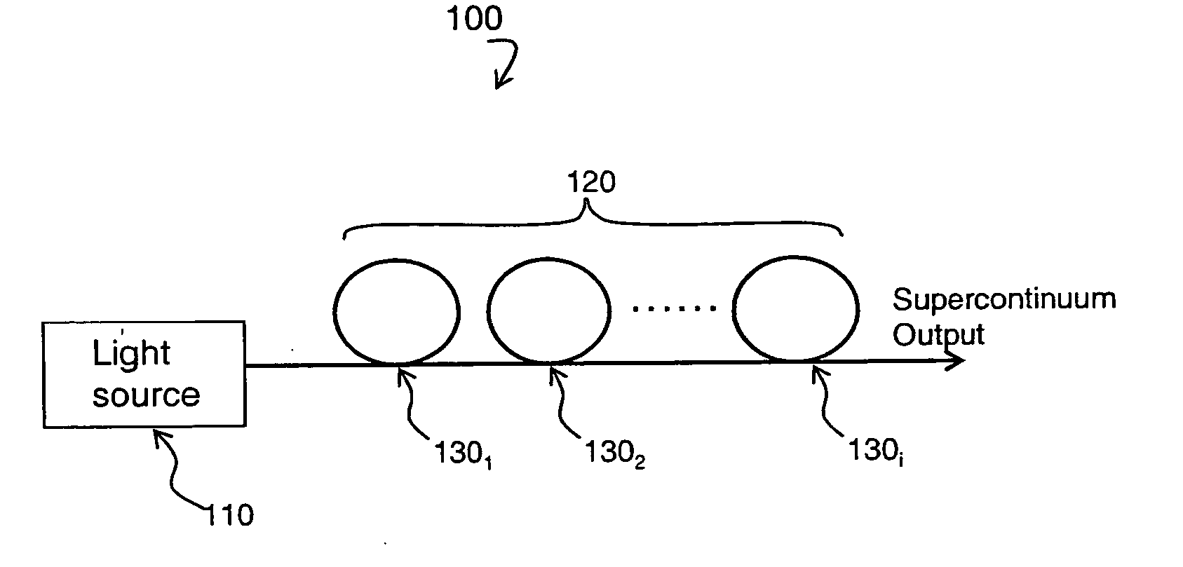
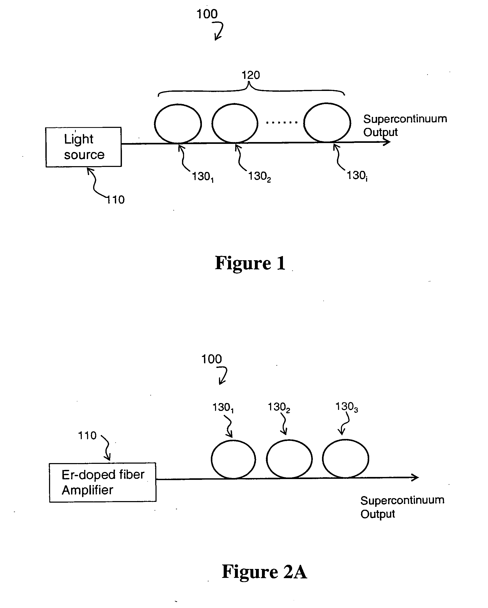
[0049] Reference will now be made in detail to the present preferred embodiments of the invention, examples of which are illustrated in the accompanying drawings. Wherever possible, the same reference numbers will be used throughout the drawings to refer to the same or like parts. An exemplary embodiment of the supercontinuum light emitting device 100 of the present invention is shown schematically in FIG. 1.

[0050] The supercontinuum light emitting device 100 of FIG. 1 includes: (i) an effectively CW light source 110 producing light of wavelength λ1 situated within the output spectrum 110A of this effectively CW light source 110; and (ii) a nonlinear fiber 120 optically coupled to the effectively CW light source 110. Although λ1 may be any wavelength situated within the output spectrum of the effectively CW light source 110, it is preferable that λ1 be either the peak wavelength or the center wavelength of the output spectrum of this effectively CW light source.

[0051] The term “no...


PUM

PropertyMeasurementUnit
Poweraaaaaaaaaa
Poweraaaaaaaaaa
Nanoscale particle sizeaaaaaaaaaa

Abstract

A supercontinuum light emitting device comprises an effectively CW light source producing light of wavelength λ1 within a specified bandwidth and a nonlinear fiber optically coupled to the light source. The nonlinear fiber has a plurality of fiber segments with different zero dispersion wavelengths λoi, where each successive fiber segment has zero dispersion wavelength λoi which is larger than the zero dispersion wavelength of the preceding fiber and the zero dispersion wavelength of the first fiber segment is within ±20 nm of λ1.

Description

BACKGROUND OF THE INVENTION [0001] 1. Field of the Invention [0002] The present invention relates generally to supercontinuum light emitting devices and methods for generation of supercontinuum by using optical fibers. [0003] 2. Technical Background [0004] It is known to generate supercontinuum by launching femtosecond duration (10−15 sec) pulses of light from the light source into the optical fiber segments. For example, the device disclosed in U.S. Pat. No. 6,775,447 utilizes an optical fiber having a plurality of nonlinear fiber sections. Those sections have zero dispersion wavelengths that are within ±200 nm of the wavelength of the light source. [0005] One of the drawbacks of the method disclosed in U.S. Pat. No. 6,775,447 is that it relies on very high peak pulse power (on the order of 10 KW or larger) to produce the supercontinuum. For example, this patent describes light pulses having about 15 KW of power (3 nJ / 200×10−15 sec). However, typically the power available from CW (...

Claims


Application Information

Patent Timeline
IPC IPC(8): G02B6/00
CPCG02B6/02242G02B6/03627G02B6/29377G02F1/353G02F2001/3507G02F2001/3528G02F1/3507G02F1/3528
Inventor KUKSENKOV, DMITRI VLADISLAVOVICHLI, SHENPINGRUFFIN, ALRANZO BOH
Owner CORNING INC
Why Eureka
Try Eureka