Capacity-changing unit of orbiting vane compressor

Inactive Publication Date: 2006-09-07
LG ELECTRONICS INC
View PDF10 Cites 21 Cited by
  • Summary
  • Abstract
  • Description
  • Claims
  • Application Information

AI Technical Summary

Benefits of technology

[0025] Therefore, the present invention has been made in view of the above problems, and it is an object of the present invention to provide a capacity-changing unit of an orbiting vane compressor having inner and outer compression chambers formed at the inside and the outside of an orbiting vane as the o

Problems solved by technology

Generally, power consumption when the operation of the compressor is initiated is greater than power consumption when the compressor is normally operated.
Furthermore, interference between the compressed gas in the compressor and the parts of the compressor is caused due to abrupt interruption of the compressor and initiation of the compressor, and therefor

Method used


Image

  • Capacity-changing unit of orbiting vane compressor
  • Capacity-changing unit of orbiting vane compressor
  • Capacity-changing unit of orbiting vane compressor

Examples


Embodiment Construction

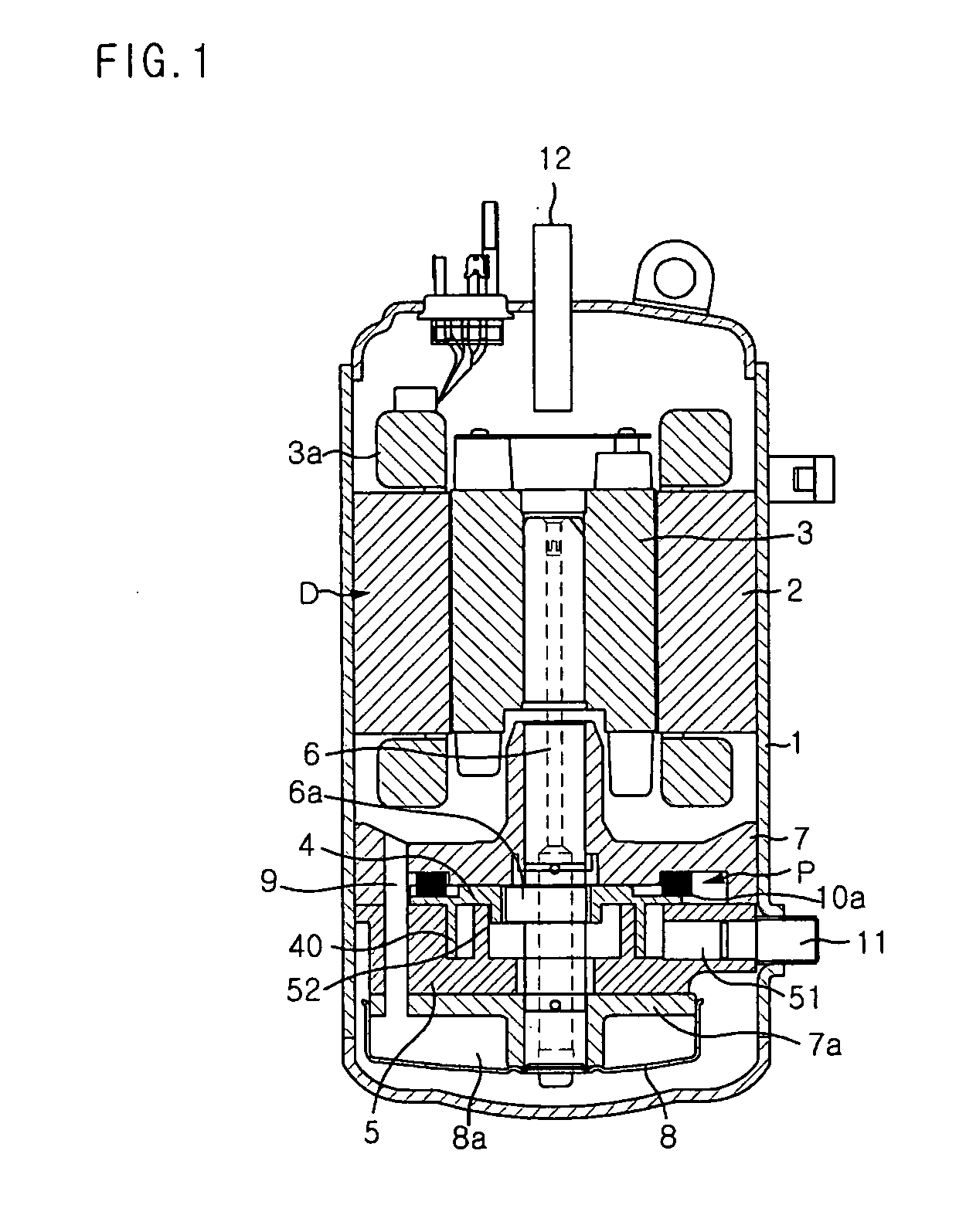
[0054] Now, preferred embodiments of the present invention will be described in detail with reference to the accompanying drawings.

[0055]FIG. 4 is an exploded perspective view illustrating a capacity-changing unit of an orbiting vane compressor according to a first preferred embodiment of the present invention.

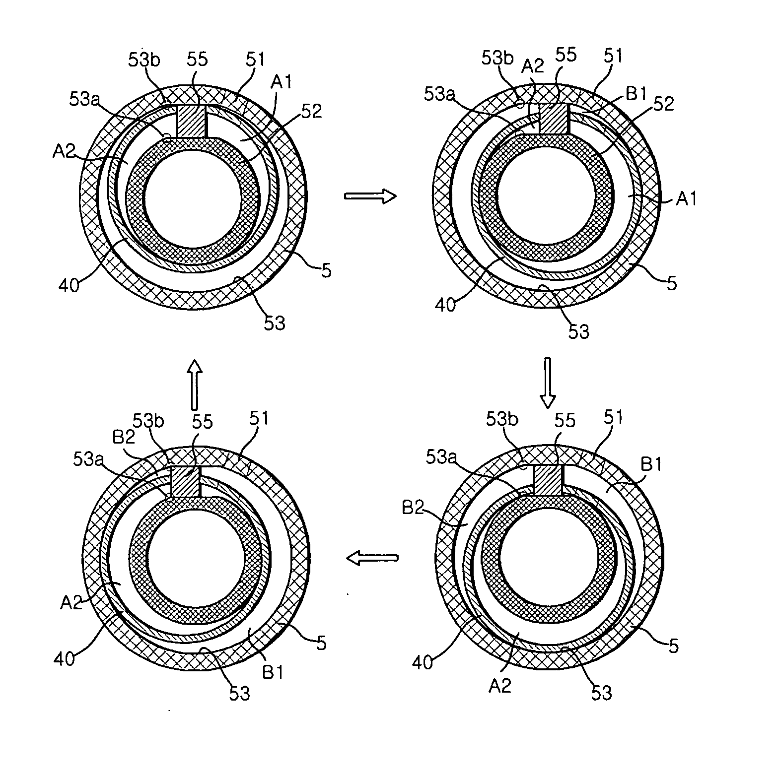
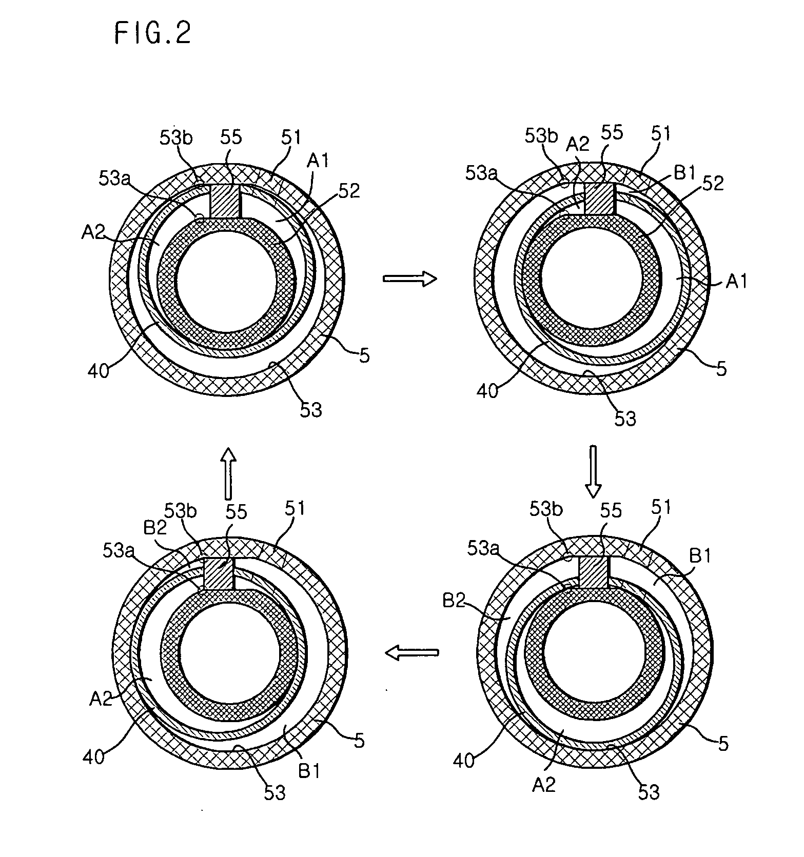
[0056] At the lower surface of a cylinder 5 is formed a valve operation groove 110 (the valve operation groove 110 is formed at the upper surface of the cylinder 5 in the drawing). The valve operation groove 110 includes a cylinder suction hole 111, which communicates with a side inlet port 51 of the cylinder 5, and inner and outer outlet ports 53a and 53b, which communicate with inner and outer compression chambers in the cylinder 5. On the valve operation groove 110 is rotatably located a rotary valve plate 120, which is formed in the same shape as the valve operation groove 110.

[0057] Referring to FIG. 5A, the rotary valve plate 120 includes a communication inlet port 12...


PUM


Abstract

Disclosed herein is a capacity-changing unit of an orbiting vane compressor that is capable of performing normal operation and no-load operation in inner and outer compression chambers through simple manipulation of a rotary valve plate, thereby easily changing the capacity of the compressor according to operation modes. The capacity-changing unit comprises a rotary valve plate disposed between a cylinder and a subsidiary frame for opening or closing a communication channel connected between an inlet port of the cylinder and inner and outer outlet ports of the cylinder as an actuator is rotated in alternating directions. Consequently, the present invention has the effect of reducing power consumption and preventing reduction in service life of the parts of the orbiting vane compressor due to repetitive on/off operation of the orbiting vane compressor, and therefore, improving the performance and reliability of the orbiting vane compressor.

Description

BACKGROUND OF THE INVENTION [0001] 1. Field of the Invention [0002] The present invention relates to an orbiting vane compressor, and, more particularly, to a capacity-changing unit of an orbiting vane compressor that is capable of performing normal operation and no-load operation in inner and outer compression chambers through simple manipulation of a rotary valve plate, thereby easily changing the capacity of the compressor according to operation modes. [0003] 2. Description of the Related Art [0004] Generally, an orbiting vane compressor is constructed to compress refrigerant gas introduced into a cylinder through an orbiting movement of an orbiting vane in the cylinder having an inlet port. Various types of orbiting vane compressors, which are classified based on their shapes, have been proposed. [0005]FIG. 1 is a longitudinal sectional view illustrating the overall structure of a conventional rotary-type orbiting vane compressor. As shown in FIG. 1, a drive unit D and a compres...

Claims


Application Information

Patent Timeline
IPC IPC(8): F16N13/20F01C1/02F04C27/00
CPCF04C2/04F04C18/045F04C28/14F04C29/00F04C18/344
Inventor HWANG, SEON-WOONGYOO, DONG-WON
Owner LG ELECTRONICS INC
Why Eureka
Try Eureka