
Concealed portable fan

a portable fan and fan body technology, applied in the field of fans, can solve the problems of unstable fan, inability to effectively cool the user, and non-elevated models positioned relatively close to the ground, and achieve the effect of less visual disturbance and stable elevated air stream

Inactive Publication Date: 2006-09-07
LASKO HLDG
View PDF34 Cites 159 Cited by
  • Summary
  • Abstract
  • Description
  • Claims
  • Application Information

AI Technical Summary

Benefits of technology

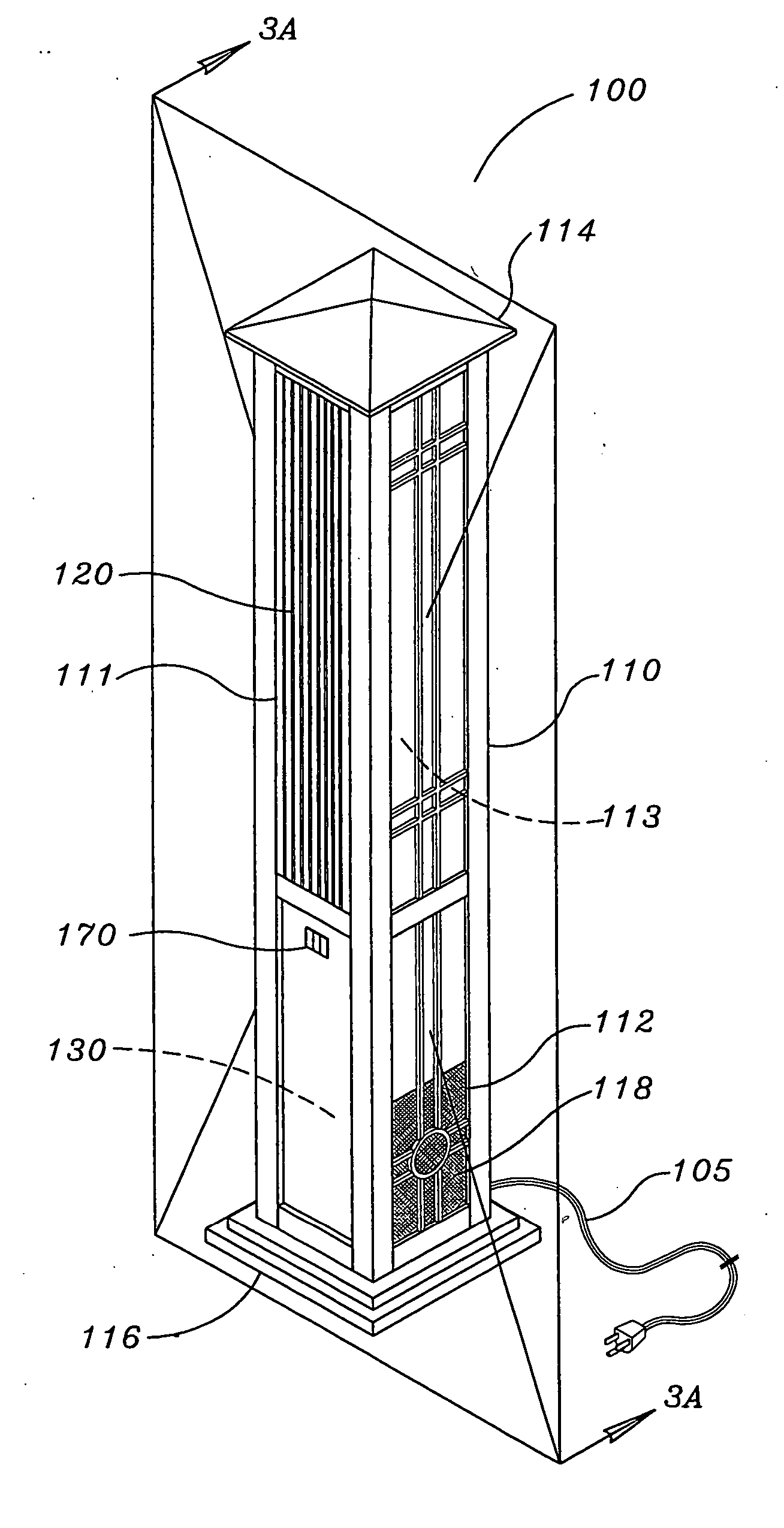
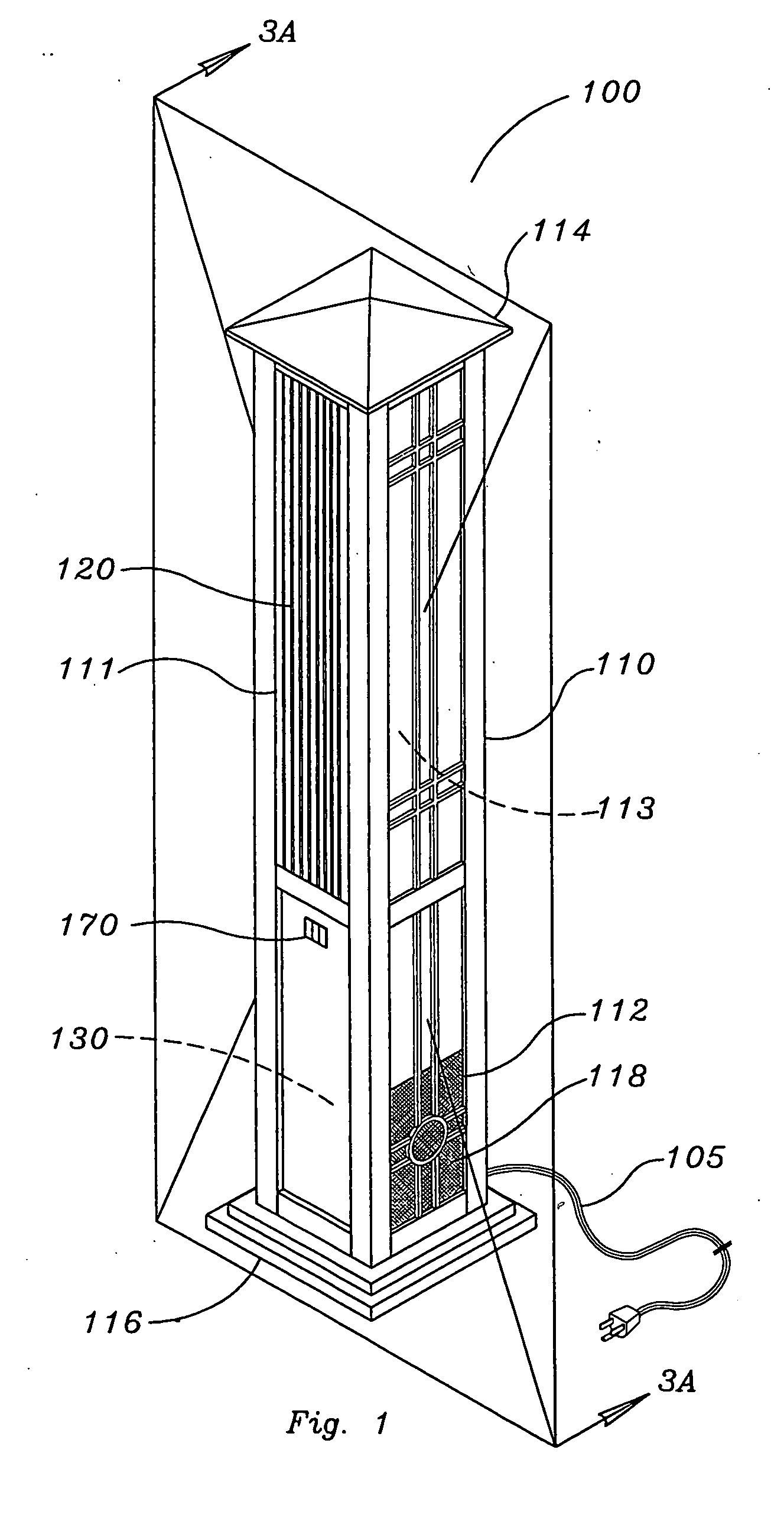
[0007] In light of the shortcomings of the prior art, the present invention is directed to a portable fan using an inventive air generator design to create a stable elevated air stream and that is conceal and thus less visually disruptive. The device overcomes several if not all of the deficiencies of conventional indoor and / or outdoor fans.
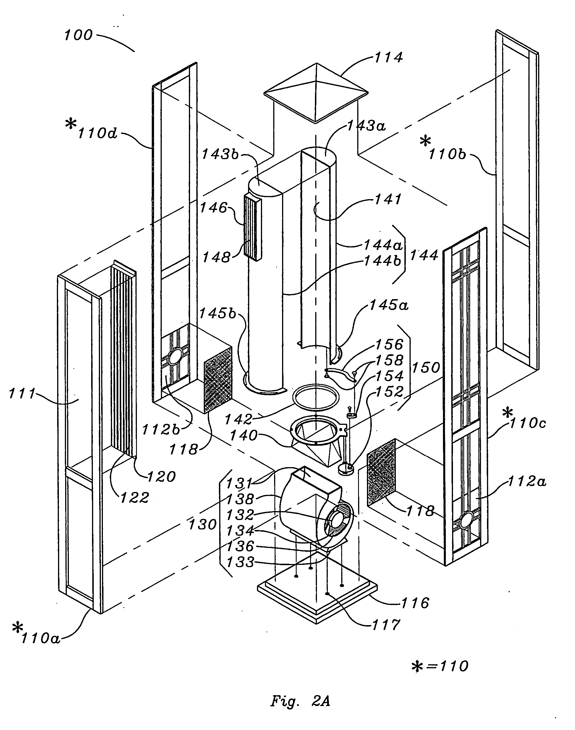
[0008] The concealed portable fan also includes an innovative panel construction. The use of this panel construction allows further innovation in materials and styles not presently associated with conventional fans.
[0009] The panel construction includes removable / replaceable / interchangeable panels that provide a portable fan that can be moved from room to room (or from indoor use to outdoor use) while still being adaptable to a particular room or environment in which the portable fan is being used. The to removable / replaceable / interchangeable panels allow the portable fan to be modified by the user to match surrounding furniture and / or blend in with the room decor thus further concealing the fan.

Problems solved by technology

There are however several disadvantages to conventional fans.
Non-elevated models that are positioned relatively close to the ground do not have the ability to effectively cool the upper body.
Likewise non-elevated models do not posses the ability to project the generated air current over objects such as furniture, thus impairing the ability to efficiently cool the user.
Both of these elements contribute to the instability of the fan and require a base of considerable size to stabilize the device during use.
The size of such a base does not permit an optimized space saving design.
The fan may also have an oscillation function, which further exacerbates the instability of the device.
Another problem with conventional fans using axial fan blades is the large volume of air produced by the blade.
One, the ability to project a large volume of air at a sufficient velocity, so as to impinge the skin of the user for the desired cooling effect requires a motor of substantial power and cost.
Two, the thrust created by projecting a large volume of air at a sufficient velocity further exacerbates the stability problem of the device.
The significant volume of air combined with the growth in the coverage area of the air stream may cause objects, (such as napkins, playing cards, etc) to be dislodged from their intended place.

Method used


Image

  • Concealed portable fan
  • Concealed portable fan
  • Concealed portable fan

Examples


Embodiment Construction

[0035] The following description is of an exemplary portable fan that generates an elevated air stream. The elevated air stream allows effectual cooling of the users upper body as well as the ability to project the air stream over furniture and other objects. The exemplary portable fan uses a high velocity low thrust air generator to mitigate the stability problems associated with axial fan blades. The non-conical shape of the air stream allows a more precise adjustment of direction when compare to conical shaped air streams.

[0036] The use of the disclosed air generators provide a compact design that does not require the use of large protective grills. Oscillation can be incorporated into the device while being less visually disruptive than axial fans. The ability to locate the mass of the motor at a low elevation with respect to a mounting surface combined with the absence of large grills further enhances the stability of the device.

[0037] The novel design of the parts and assemb...


PUM


Abstract

A stable portable fan capable of generating an exhaust air stream elevated above a support surface allowing the exhaust air stream to be directed as desired by the user is provided. The device includes an air generator assembly located within a polygonal column generating an exhaust air stream that exiting the polygonal column. The polygonal column of the device is used to disguise / conceal the fan.

Description

CROSS-REFERENCE APPLICATIONS [0001] This application claims priority to provisional patent application 60 / 688,970 filed Apr. 28, 2005 and provisional patent application 60 / 702,802 filed Jul. 27, 2005. This application is also a Continuation-in-Part of application Ser. No. 10 / 944,290, filed Sep. 16, 2004, which is a Continuation-in-Part of application Ser. No. 10 / 347,079, filed Jan. 17, 2003, which is a Continuation-in-Part of application Ser. No. 10 / 322,169 filed Dec. 18, 2002 now U.S. Pat. No. 6,760,543. This application is also a Continuation-in-Part of application Ser. No. 10 / 720,374 filed Nov. 24, 2003, which is a Continuation-in-Part of application Ser. No. 10 / 431,964, filed May 8, 2003 now U.S. Pat. No. 6,943,256, which is a Continuation-in-Part of application Ser. No. 10 / 347,079, filed Jan. 17, 2003, which is a Continuation-in-Part of application Ser. No. 10 / 322,169 filed Dec. 18, 2002 now U.S. Pat. No. 6,760,543.FIELD OF THE INVENTION [0002] This invention relates generally ...

Claims


Application Information

Patent Timeline
Patent Type & Authority Applications(United States)
IPC IPC(8): F24F7/00
CPCF24F7/065F24F2221/12
Inventor LASKO, WILLIAM E.ORR, PAUL W.WILSON, RODNEY
Owner LASKO HLDG
Learn More