
System and method for dynamic ordering in a network processor

Inactive Publication Date: 2006-09-07
CISCO TECH INC
View PDF16 Cites 47 Cited by
  • Summary
  • Abstract
  • Description
  • Claims
  • Application Information

AI Technical Summary

Benefits of technology

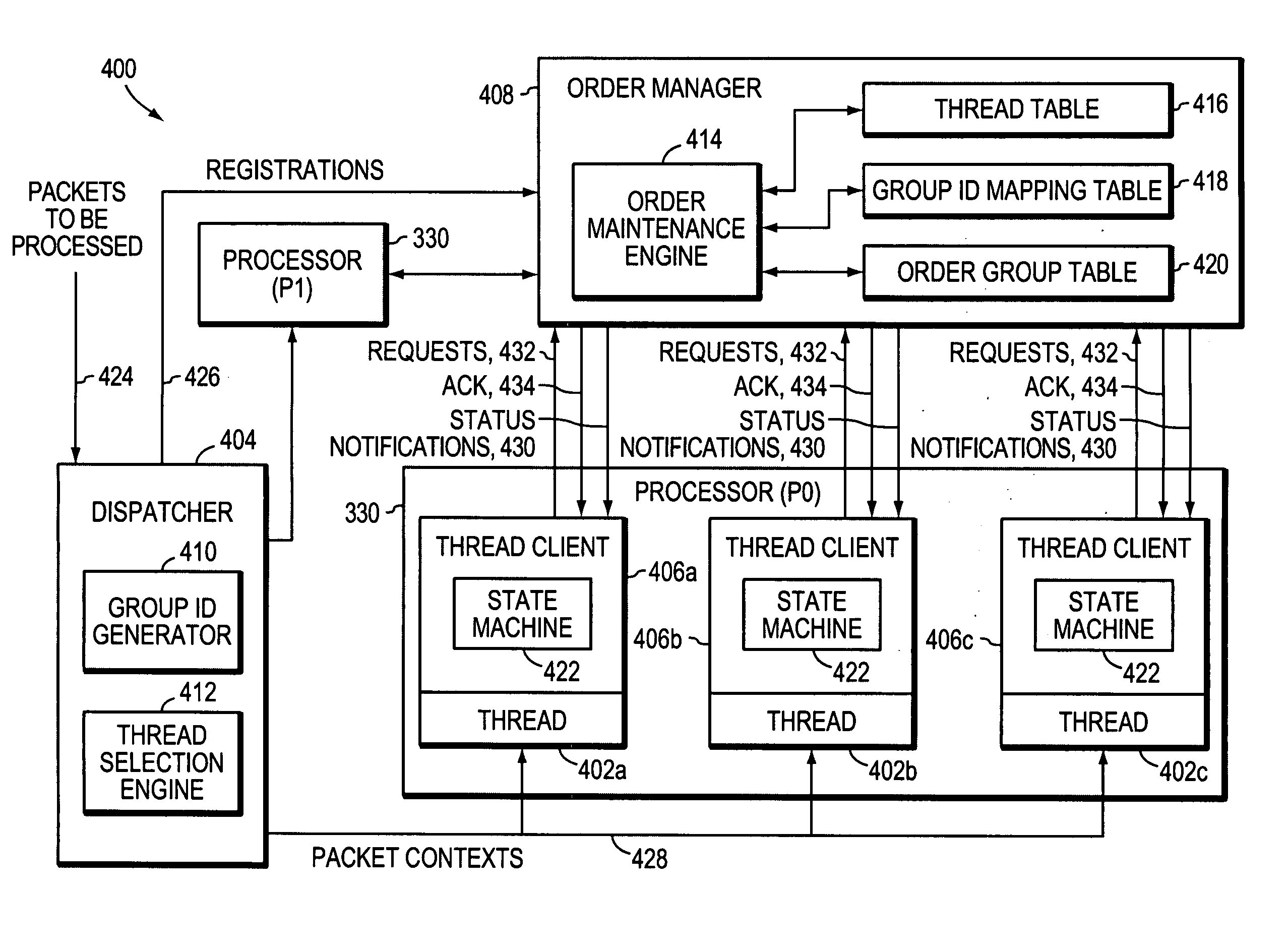
[0012] More specifically, the dispatcher preferably generates a context for received packets and selects an initial or primary Group Identifier (ID) for the context. The initial Group ID specifies the first order group for the context. The dispatcher then identifies a free thread and passes the packet context to it for processing. The dispatcher also registers the Group ID and the ID of the thread to which the packet context has been assigned with the order manager. In the illustrative embodiment, the order manager stores this information in a plurality of tables, which are used to generate an order status that indicates, for each Group ID, and thus for each order group, which thread is at the head of line (HOL) for that Group ID. The thread clients prevent their respective threads from performing certain actions, such as accessing a shared resource, e.g., memory, or releasing the packet being processed, until the thread reaches the HOL for its order group. Nonetheless, a thread may perform actions that are not order-sensitive before the thread reaches the HOL. Furthermore, a thread may change order groups dynamically during the processing of a single packet. Nonetheless, the threads belonging to each order group are maintained in order relative to each other.

Problems solved by technology

One problem with shared resources, however, is that packets received by the intermediate node in a given order may be processed and forwarded in a different order.
However, if a processor stalls or otherwise cannot complete its processing within the phase interval, all processors of the array stall in order to maintain FIFO ordering.

Method used


Image

  • System and method for dynamic ordering in a network processor
  • System and method for dynamic ordering in a network processor
  • System and method for dynamic ordering in a network processor

Examples


Embodiment Construction

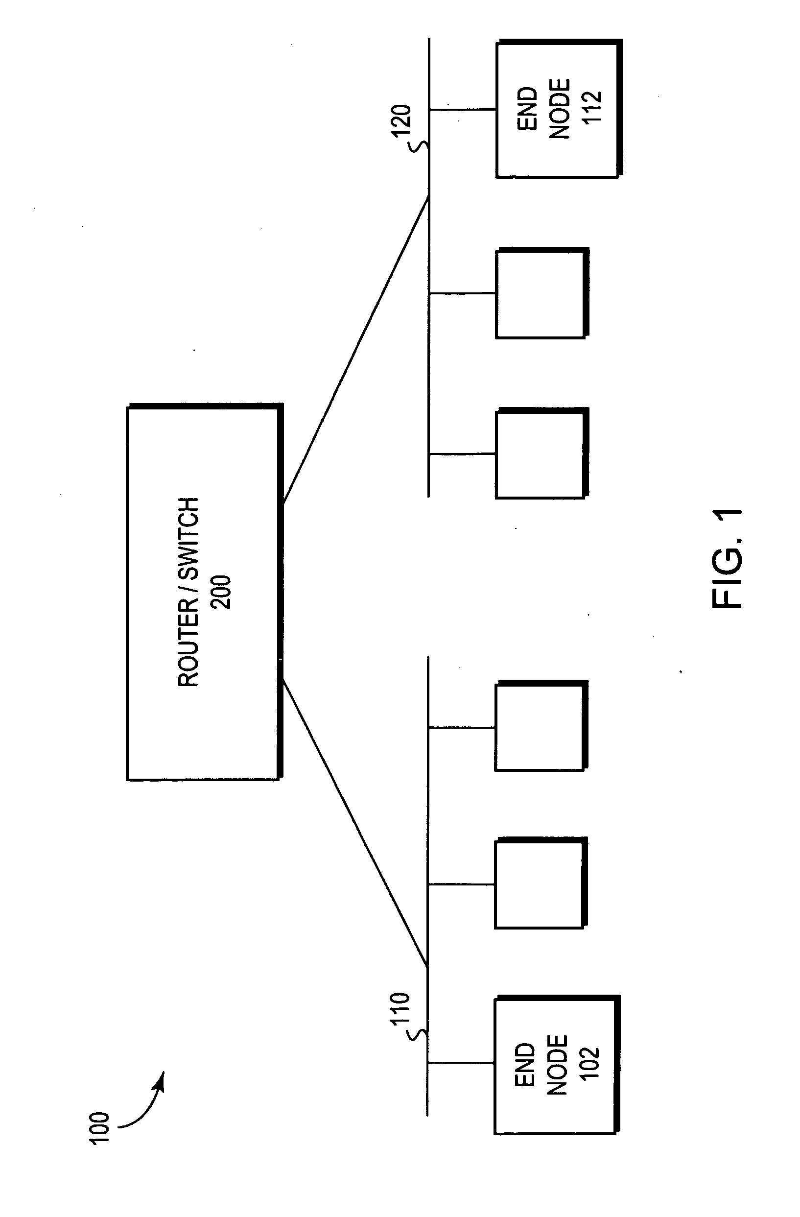
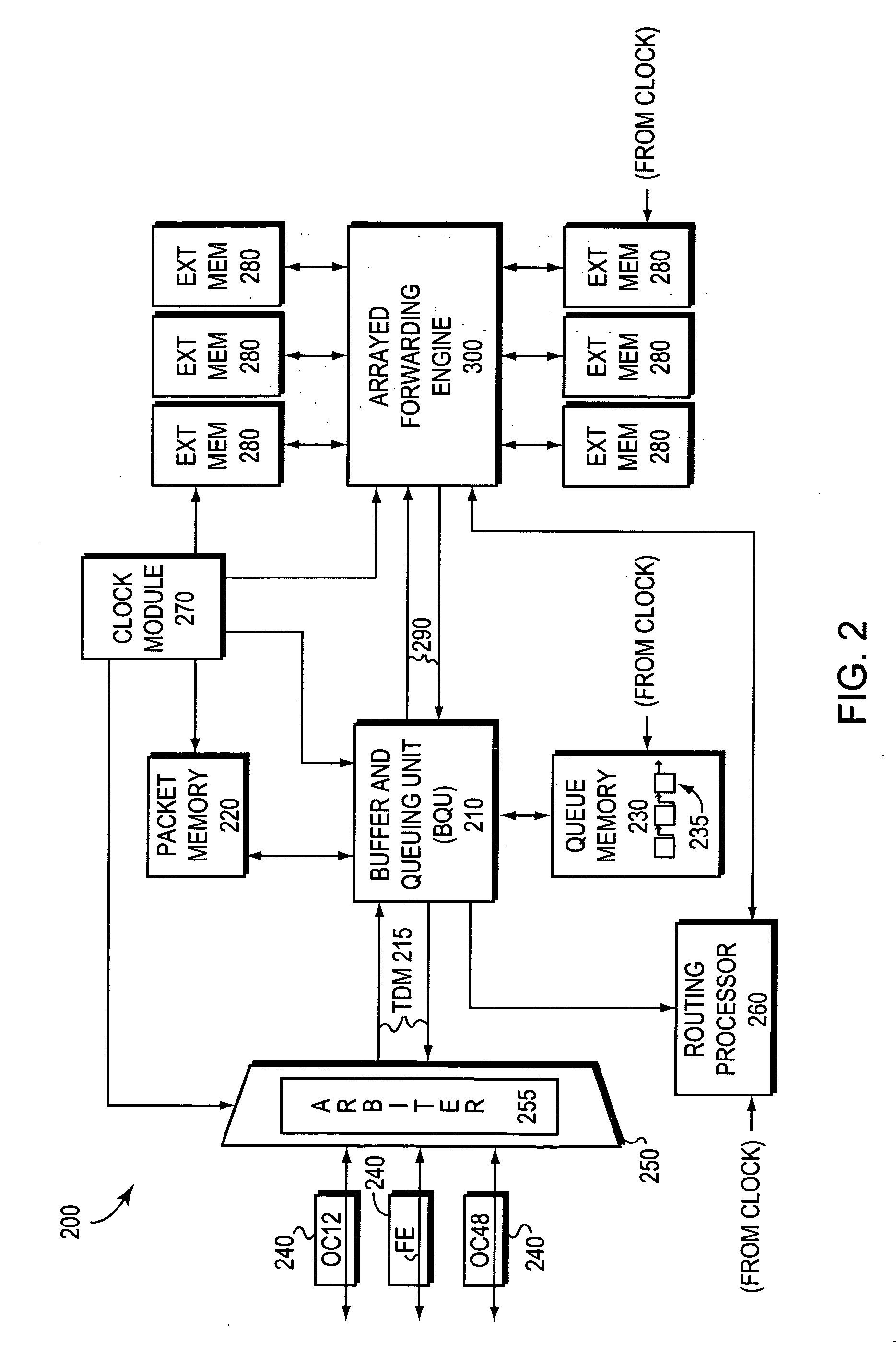
[0020]FIG. 1 is a block diagram of a computer network 100 comprising a collection of interconnected communication media and subnetworks attached to a plurality of stations. The stations are typically computers comprising end nodes 102, 112 and intermediate network node 200. The intermediate node 200 may be a router or a network switch, whereas the end nodes 102, 112 may include personal computers, workstations, servers, personal digital assistants (PDAs), etc. The subnetworks generally comprise local area networks (LANs) 110 and 120, although the invention may work advantageously with other communication media configurations such as point-to-point network links, wide area networks (WANs), wireless networks, etc. Communication among the stations of the network is typically effected by exchanging discrete network messages, such as frames or packets, between the communicating end nodes according to a predefined protocol, such as the Internet protocol (IP), the Internet Packet Exchange ...


PUM


Abstract

A system and method maintains order among a plurality of threads in a multi-threaded processing system. The processing system, which may be disposed at an intermediate network device, has a plurality of processors each supporting a plurality of threads. The ordering system includes a dispatcher that assigns work, such as the processing of received packets to free threads, an order manager that keeps track of the relative order of the threads, and a thread client associated with each thread for enforcing the determined order. Packets to be processed by the processing system are assigned to an initial order group by the order manager based on a selected attribute, and those packets sharing the same attribute value are assigned to the same order group. During processing, a thread may request reassignment to other order groups in response to other attributes of the packets. The order manager preferably manages the switching of threads among order groups and ensures that the threads within each order group process their packets in order.

Description

BACKGROUND OF THE INVENTION [0001] 1. Field of the Invention [0002] The present invention generally relates to multiprocessor systems and, more specifically, to the order by which multiple processors execute instructions. [0003] 2. Background Information [0004] High-performance computer systems often utilize multiple processors or central processing units (CPUs). Each processor may have access to shared and / or private data, such as program instructions, e.g., algorithms, that are stored in a memory coupled to the processors. In addition, each processor may support one or many threads, where each thread corresponds to a separate instruction or execution sequence. One of the more common multiprocessor architectures is called a systolic array in which each processor is coupled to its nearest neighbors in a mesh-like topology, and the processors perform a sequence of operations on the data that flows between them. Typically, the processors of a systolic array operate in “lock-step” with...

Claims


Application Information

Patent Timeline
Patent Type & Authority Applications(United States)
IPC IPC(8): G06F9/46G06F9/44G06F9/48
CPCG06F8/45G06F9/4843
Inventor POTTER, KENNETH H. JR.
Owner CISCO TECH INC
Learn More