Area contact truss strut joint

a strut joint and area contact technology, applied in the direction of girders, joists, trusses, etc., can solve the problems of reducing the overall stiffness and load carrying capacity of the truss, and achieve the effect of improving the overall stiffness of the truss and the load carrying capacity

Inactive Publication Date: 2006-09-14
DAVIS JOHN D
View PDF7 Cites 4 Cited by
  • Summary
  • Abstract
  • Description
  • Claims
  • Application Information

AI Technical Summary

Benefits of technology

[0008] In alternate embodiments, an interposing structure may be added to the strut joint. It may be placed between the strut ends and the chords to either partially extend the trough surface for an enlarged area contact with the strut end. Alternately, the interposing structure may provide entire trough surface whereby a reduction of the chord's cross section due to the trough is circumvented while the advantageous area contact is maintained. The interposing structure may rest on the inner chord face. Positioning of the interposing structure may be provided by a positioning groove fabricated into the inner chord face and / or a corresponding positioning feature of the interposing structure. The interposing structure may be part of a prefabricated assembly including lateral joint plates. The preassembly may clamp along the chords in a friction contact and be aligned with a positioning label on the chords indicating the predetermined position of the strut joint. As a favorable result of the area contact, overall truss stiffness and load carrying capacity may be improved without increasing dimensions of struts and / or chords

Problems solved by technology

This may eventually reduce the overall stiffness and load carrying capacity of the truss 10.

Method used


Image

  • Area contact truss strut joint
  • Area contact truss strut joint
  • Area contact truss strut joint

Examples


Embodiment Construction

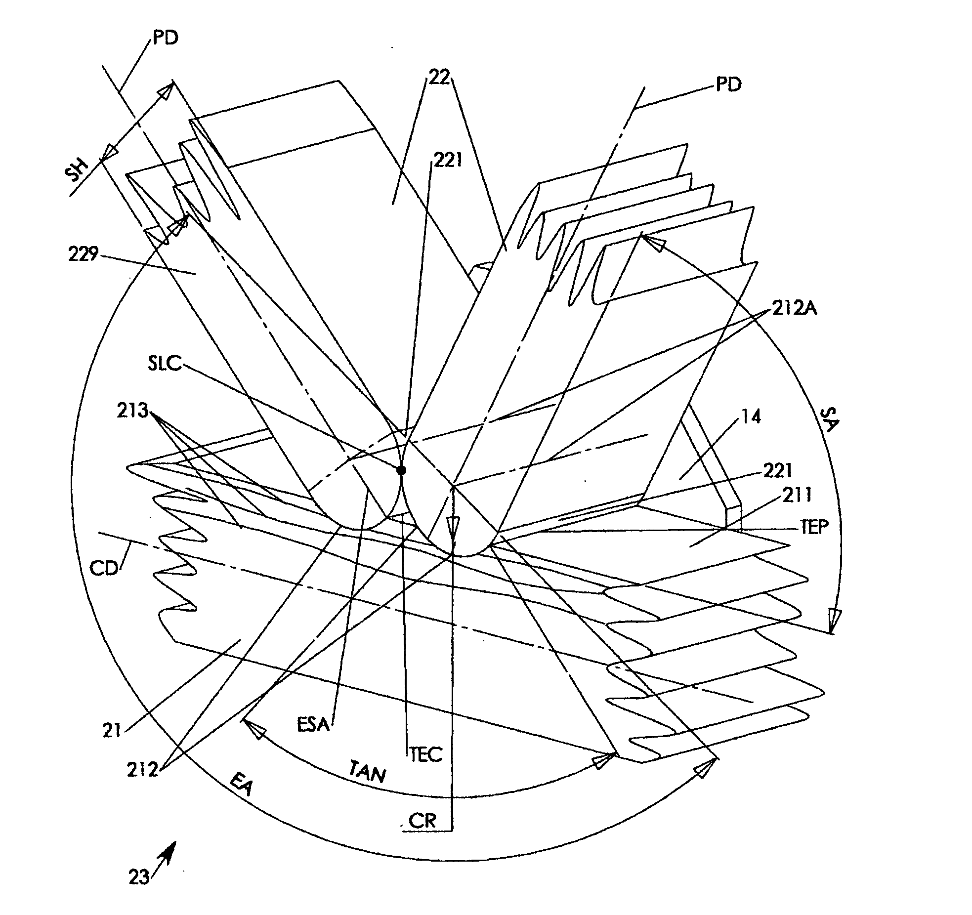
[0018] The present invention introduces improved strut joints 23 of FIGS. 4-7 with area contact at least in an interface between a chord trough 212 and a strut end surface 221 between the modified struts 22 and inner chord faces 211 of modified chords 21 as depicted in FIGS. 4, 5. Area contact may also extend directly between adjacent modified chord end surfaces 221 of a modified strut joint 23 as illustrated in FIGS. 6, 7.

[0019] Primary area contact is provided between at least rotationally symmetric strut end surfaces 221 and corresponding at least rotationally symmetric contact troughs 212. The contact troughs 212 are rotationally symmetric with respect to a trough axis 212A that is substantially perpendicular to the truss symmetry plane SP, a chord protrusion direction CD, a strut protrusion direction PD and parallel to the strut tilt axes TA. As a result, the struts 22 may be combined with the inner chord faces 211 in a primary area contact irrespective their strut joint angle...


PUM


Abstract

A strut joint of a truss features a contact trough on an inner chord face being in an area contact with a rotationally symmetric strut end surface having a contact radius of at least half a strut height. The rotation axis of the strut end surface and the trough is substantially perpendicular to the struts protrusion direction and the chord's protrusion direction. The area contact provides for snug contact irrespective deviations from a predetermined strut joint angle between strut end and chord. An optional interposing structure may extend the area contact in between two opposite strut end surfaces of a single strut joint.

Description

CROSS REFERENCE [0001] The present Application claims priority from Provisional Application of the same title and inventor, filed Mar. 08, 2005, Ser. No. 60 / 659,988, which is hereby incorporated by reference.FIELD OF INVENTION [0002] The present invention relates to trusses having chords and struts. More particular, the present invention relates to trusses having strut joints with rotationally symmetric area contact between strut and chord. BACKGROUND OF INVENTION [0003] The load carrying capacity of a truss greatly depends on the rigidity of the strut joints where web struts of a truss are combined with the chords. A prior art truss 10 as shown in FIG. 1 includes top and bottom chords 11 combined along their respective inner chord faces 111 via a number of web struts 12. The ends of the web struts 12 define at their attachment locations on the inner chord faces 111 together with the chords 11 the strut joints 13. The web struts 12 are attached to the chords 111 in varying strut joi...

Claims


Application Information

Patent Timeline
Patent Type & Authority Applications(United States)
IPC IPC(8): E04C3/02
CPCE04C3/17
Inventor DAVIS, JOHN D.
Owner DAVIS JOHN D
Why Eureka
Try Eureka