Solar collection apparatus and methods

a technology of solar collectors and solar energy, applied in solar heat systems, lighting and heating apparatus, instruments, etc., can solve the problems of not being widely adopted

Inactive Publication Date: 2006-09-14
SEESCAN
View PDF7 Cites 66 Cited by
  • Summary
  • Abstract
  • Description
  • Claims
  • Application Information

AI Technical Summary

Benefits of technology

[0006] In accordance with the present invention a solar tracking apparatus has a mirror or other reflecting surface for collecting and reflecting incident solar radiation. The mirror is supported for independent motion about a pair of axes. An accelerometer generates signals representative of an amount and direction of motion of the mirror about each of

Problems solved by technology

There are many variations of the foregoing devices, but to date, none has been widely adop

Method used


Image

  • Solar collection apparatus and methods
  • Solar collection apparatus and methods
  • Solar collection apparatus and methods

Examples


first embodiment

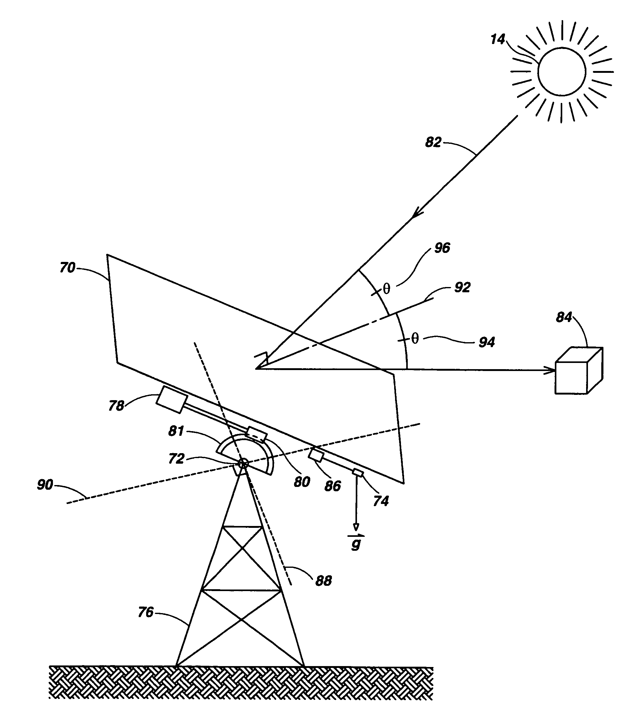
[0025]FIG. 4 illustrates the present invention that utilizes a flat mirror to heat a target. A solar tracking apparatus has a mirror 70 or other reflecting surface for collecting and reflecting incident solar radiation 82 from the Sun 14. The mirror in this embodiment has a planar configuration, although this embodiment could be adapted to use other mirror configurations including parabolic dish, parabolic trough, etc. in order to concentrate the incident solar radiation. The mirror could be conventional silver coated glass, or could be plastic, or could be Mylar® polyester film on a support substrate, or some other form of reflective material that is durable, lightweight and inexpensive.

[0026] The mirror 70 (FIG. 4) is supported by a pair of pivot mechanisms 72 for independent motion about a pair of tilt axes 88 and 90. The pivot mechanisms 72 are mounted atop a support tower 76. An accelerometer 74 generates signals representative of an amount and direction of motion of the mirror...

second embodiment

[0030]FIG. 5 illustrates the present invention that utilizes an array 104 of individual mirrors 106 to reflect solar radiation 110 through a skylight 102 on the roof of a building 100 to provide internal lighting. This greatly increases the amount of solar radiation otherwise directly entering the interior of the building through the skylight 102 as illustrated by incident light rays 108. The mirrors 106 may each be independently supported and moved as illustrated in FIG. 4 or they may be simultaneously supported and moved by a common tracking system so that reflected light 114 strikes a fixed angle target mirror 112 and is reflected as downwardly projected light 116. The skylight 102 may be of the type sold under the SOLATUBE® trademark which employs a conduit with a highly reflective surface. Optionally a hot mirror 118 may be inserted into the reflected light transmission path to reflect away the infrared component during the Summer to avoid unwanted heating of the interior of th...

embodiment 400

[0039]FIGS. 14-20 illustrate another embodiment of the present invention that utilizes weight-tensioned mechanisms to pivot the mirror. The embodiment 400 includes a planar square mirror 402 whose corners are supported by four cable hook corners 404. A small yoke 406 (FIGS. 15 and 19) has a square surface which is secured to the center of the rear side of the mirror 402 by suitable adhesive. Small yoke 406 is connected for independent rotation about two axes to a tall yoke 408 by a cross piece 410. The base of the tall yoke 408 is secured by screws 412 and nuts 414 (FIG. 19) to a cylindrical cap plate 416. The cylindrical cap plate 416 is mounted on the upper end of a support structure in the form of a hollow vertical support post 418.

[0040] A lower tension wire 420 (FIG. 18) has one end connected to the uppermost cable hook corner 404 and its other end connected to the lowermost cable hook corner 404. An upper tension wire 422 (FIGS. 18 and 19) has an intermediate segment wrapped a...


PUM


Abstract

A mirror or other reflecting surface is used for collecting and reflecting incident solar radiation. The mirror is supported for independent motion about a pair of axes. An accelerometer generates signals representative of an amount and direction of motion of the mirror about each of the axes. Motors or other drive mechanisms independently drive the mirror about each of the axes. A tracking device provides information about the current position of the Sun. A control is connected to the accelerometer, the motors and the tracking device for maintaining a predetermined optimum orientation of the mirror as the Sun moves across the sky.

Description

FIELD OF THE INVENTION [0001] The present invention relates to systems and methods for utilizing the energy of the Sun, and more particularly, to systems and methods for tracking the Sun to re-direct and concentrate incident solar radiation for lighting, heating and photovoltaic applications. BACKGROUND OF THE INVENTION [0002] Increased usage of renewable energy sources such as solar radiation is important in reducing dependence upon foreign sources of oil and decreasing green house gases. Devices have been developed in the past that track the motion of the Sun to re-direct and concentrate incident solar radiation. FIG. 1 illustrates one example of a prior art device that utilizes a parabolic dish mirror 10 with a central axis 12 that is pointed generally toward the Sun 14. Incident solar radiation 22 is received and reflected by the parabolic dish mirror 10 and concentrated at its focus 16, where a thermal target (not illustrated) can be mounted so that it can be heated. The parabo...

Claims


Application Information

Patent Timeline
IPC IPC(8): F24J2/38F24S50/20
CPCF24J2/16F24J2/38F24J2/5424Y02E10/47Y02E10/52H01L31/0547F24S30/455F24S50/20F24S23/77
Inventor OLSSON, MARK S.BYERS, RANSOM H.
Owner SEESCAN
Why Eureka
Try Eureka