Filter apparatus and droplet ejection device
a filter apparatus and droplet ejection technology, which is applied in the direction of moving filter element filters, filtration separation, separation processes, etc., can solve the problems of deterioration in ink ejection performance, increase in the size of the recording head at which the filter is provided, etc., and achieve the effect of avoiding deterioration in droplet ejection performance and restricting the enlargement of the droplet ejection head
- Summary
- Abstract
- Description
- Claims
- Application Information
AI Technical Summary
Benefits of technology
Problems solved by technology
Method used
Image

Examples
first embodiment
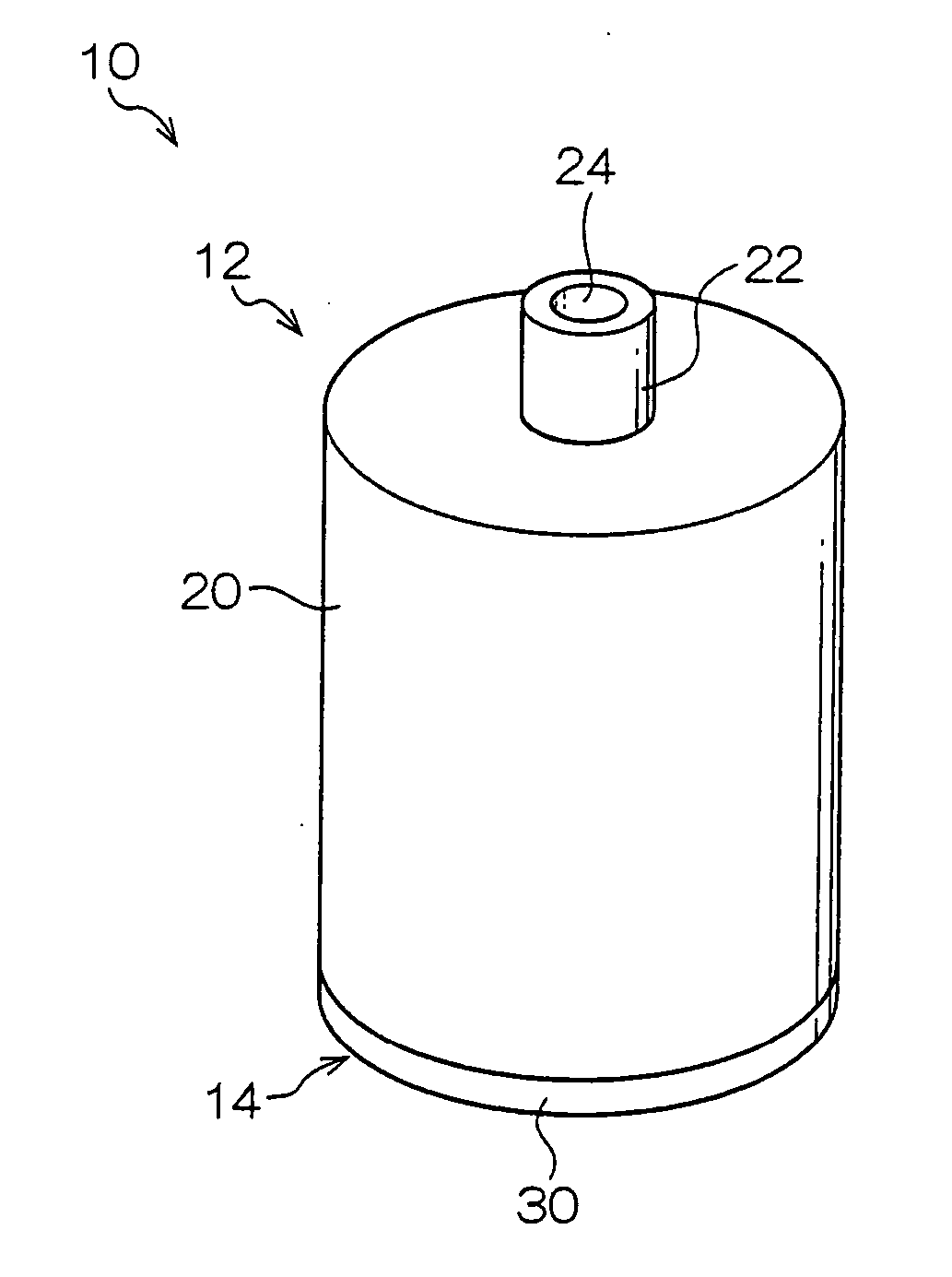
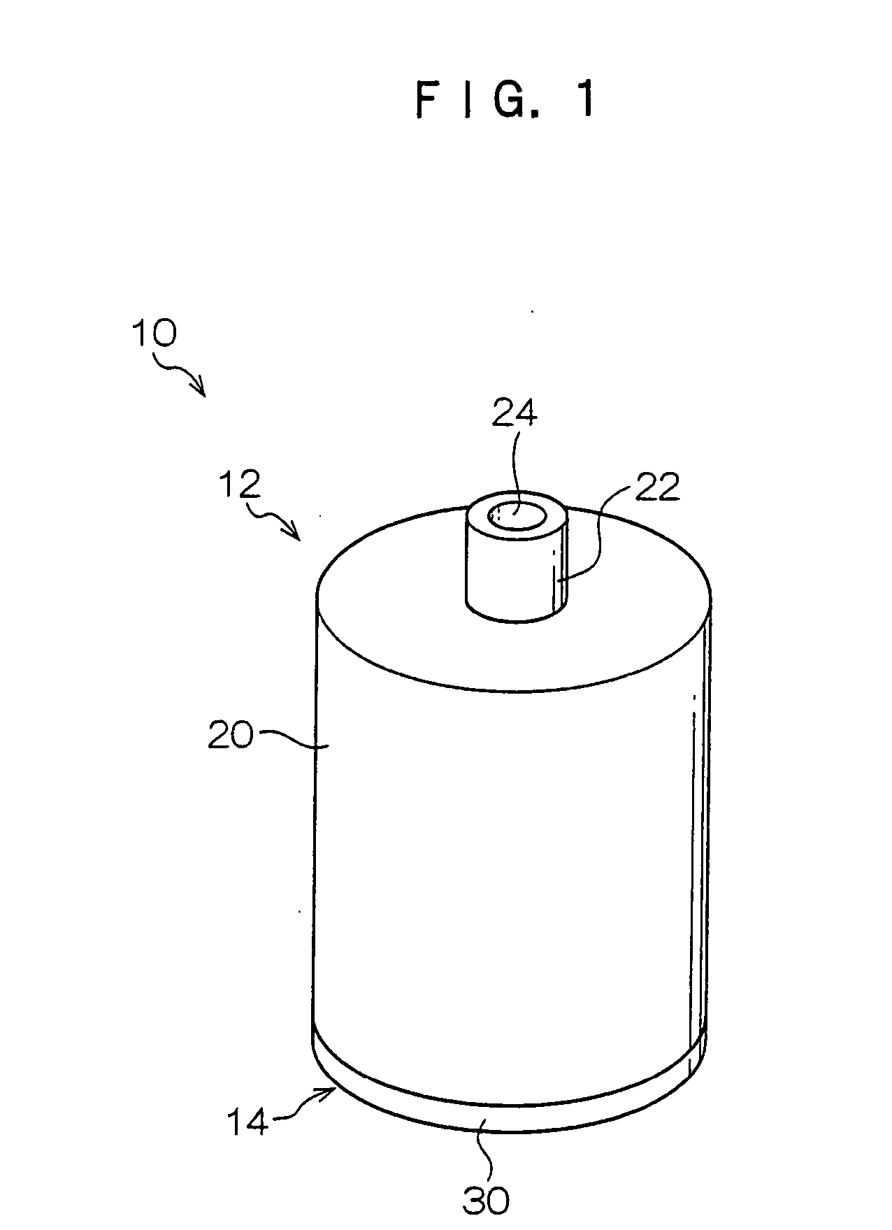
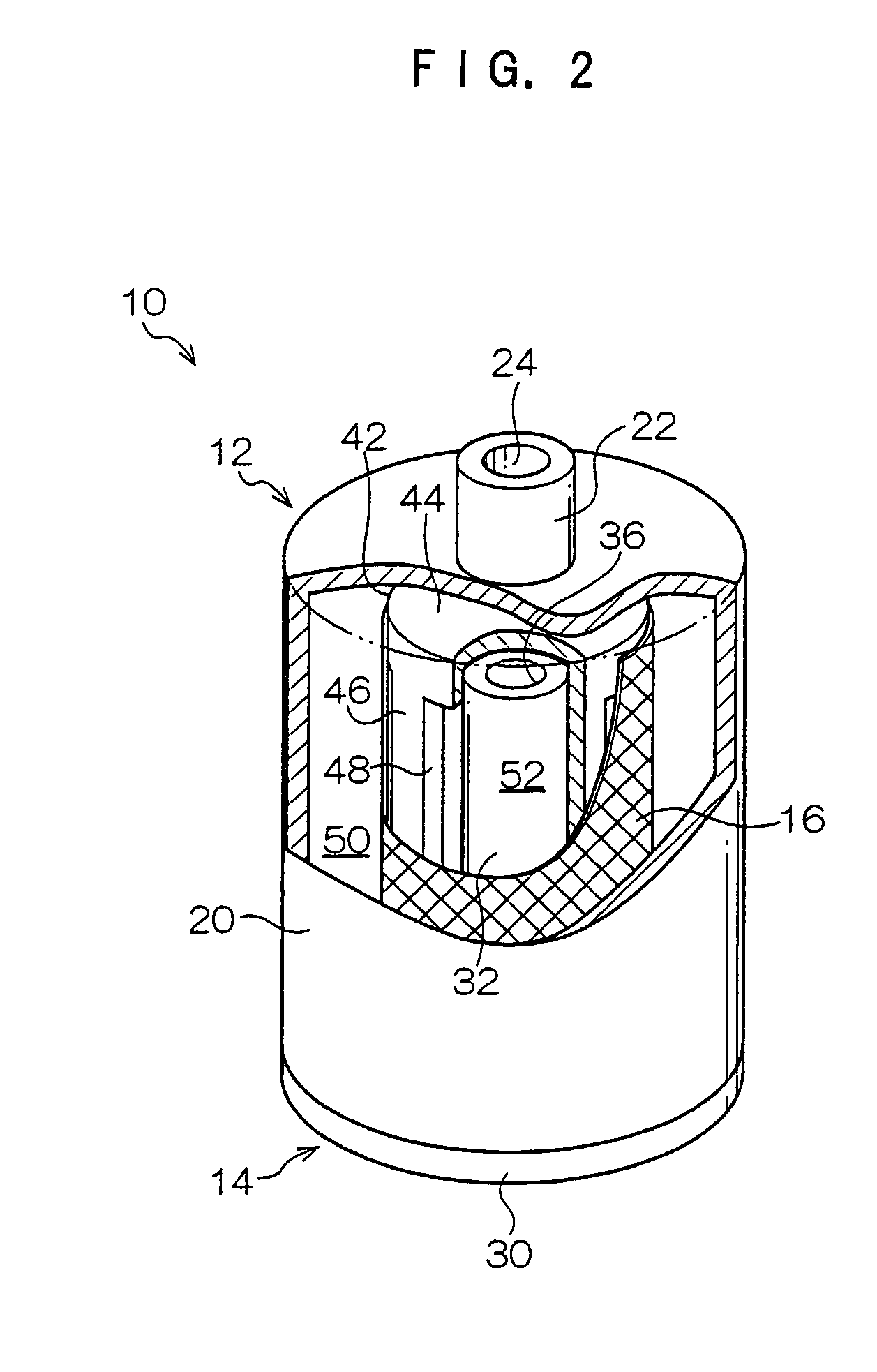
[0043] A filter unit 10 of the present embodiment is shown in FIGS. 1 and 2. As shown in the drawings, the filter unit 10 has a cylindrical form. The filter unit 10 is formed as a unit in which structural members of the filter unit 10, which will be described below, are integrally assembled. In the form of this unit, the filter unit 10 is connected at an ink supply path between an inkjet recording head and an ink cartridge, which are mounted at an inkjet recording device.
[0044] As shown in FIG. 3, the filter unit 10 is structured by a casing member 12, a cap member 14 and a filter 16.
[0045] The casing member 12 is provided with a case main body 20 formed in a hollow circular tube shape, a lower face of which includes a circular opening. A circular tube-form upstream side connection portion 22 is provided protruding from an axial center portion of a circular upper face of the case main body 20. A circular through-hole is formed in the upstream side connection portion 22 to pass the...
second embodiment
[0062] As shown in FIGS. 6A, 6B, 7A and 7B, a filter unit 60 relating to a second embodiment is formed in a flat-form substantially trapezoid solid shape. This filter unit 60 is used at an inkjet recording device with a structure which supplies ink from an ink tank through a circulation-type ink supply path (an ink circulation flow path) to a recording head. Similarly to the first embodiment, structural members of the filter unit 60 are integrally assembled to be formed into a unit.
[0063] As shown in FIGS. 6A to 8E, the filter unit 60 is structured with a casing member 62, two side plate members 64 and two filters 66.
[0064] The casing member 62 is provided with a case main body 70 in a substantially trapezoid tube form, of which a front face and a rear face are opened in the directions shown in FIGS. 6A and 6B, and whose interior is formed as a cavity. A left portion and a right portion of an upper face of the case main body 70 are respectively formed as substantially horizontal f...
third embodiment
[0086] A third embodiment is a usage example of a case in which the filter unit 60 of the second embodiment is mounted at an inkjet recording head 100.
[0087] As shown in FIGS. 10A and 10B, the inkjet recording head 100 relating to the present embodiment, which serves as a droplet ejection device, is formed in a rectangular shape. A lower face of the inkjet recording head 100 in the drawings serves as a nozzle face 102, at which numerous nozzles for ejecting ink droplets (arrow id) are formed. The filter unit 60 is mounted at an upper face of the inkjet recording head 100.
[0088] Furthermore, as shown in the drawings, the nozzle face 102 and the upper face of the inkjet recording head 100 are formed with areas substantially the same as a lower face of the filter unit 60. When the downstream side connection portion 86 of the filter unit 60 is to be connected for assembly to the inkjet recording head 100, the upper face of the inkjet recording head 100 and the lower face of the filter...
PUM
| Property | Measurement | Unit |
|---|---|---|
| shape | aaaaa | aaaaa |
| frequency | aaaaa | aaaaa |
| pressure | aaaaa | aaaaa |
Abstract
Description
Claims
Application Information
 - R&D
- Intellectual Property
- Life Sciences
- Materials
- Tech Scout
- Unparalleled Data Quality
- Higher Quality Content
- 60% Fewer Hallucinations
Browse by: Latest US Patents, China's latest patents, Technical Efficacy Thesaurus, Application Domain, Technology Topic, Popular Technical Reports.
© 2025 PatSnap. All rights reserved.Legal|Privacy policy|Modern Slavery Act Transparency Statement|Sitemap|About US| Contact US: help@patsnap.com