Electronic instrument

a technology of electronic instruments and springs, applied in the direction of electrical apparatus casings/cabinets/drawers, cell components, coupling device connections, etc., to achieve the effect of restrainting the spring force for battery ejection and increasing the spring for

Inactive Publication Date: 2006-09-14
SONY CORP
View PDF3 Cites 12 Cited by
  • Summary
  • Abstract
  • Description
  • Claims
  • Application Information

AI Technical Summary

Benefits of technology

[0014] In the electronic instrument of the embodiment of the invention, the second shaft portion is contacted to one end of the second bearing portion provided in the housing by spring force generated by the spring force generation portion (pressure contact), thereby desired pre-load can be applied to a tip of the spring for battery ejection. Accordingly, a battery can be surely ejected to a position of the tip of the spring for battery ejection by the pre-load. Moreover, when the spring force generation portion of the spring for battery ejection is pressed by the battery that has been inserted into the battery accommodating section, the second shaft portion is moved in a runout direction within the second bearing portion, thereby increase in spring force of the spring for battery ejection is restrained.

Problems solved by technology

However, there have been the following problems in the electronic instrument using the coil spring 201 for the spring for battery ejection in the related art.

Method used


Image

  • Electronic instrument
  • Electronic instrument
  • Electronic instrument

Examples


Embodiment Construction

[0067] Hereinafter, an electronic instrument of the invention is described in order of a (1) general configuration of the electronic instrument as a whole, and (2) configuration of a spring for battery ejection, (3) configuration of a cap of a battery accommodating section, (4) configuration of a battery release lever, (5) configuration of a cap of a memory card accommodating section, (6) configuration of a housing, (7) configuration of a barrier, (8) configuration of a roller, (9) configuration of a barrier slide guide portion, (10) configuration of a toggle spring, and (11) configuration of a strap fitting.

(1) General Configuration of the Electronic Instrument as a Whole

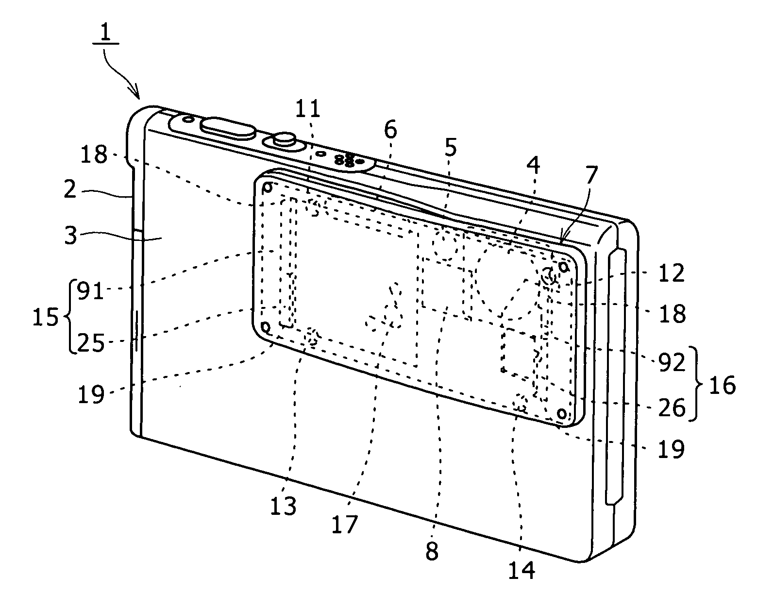
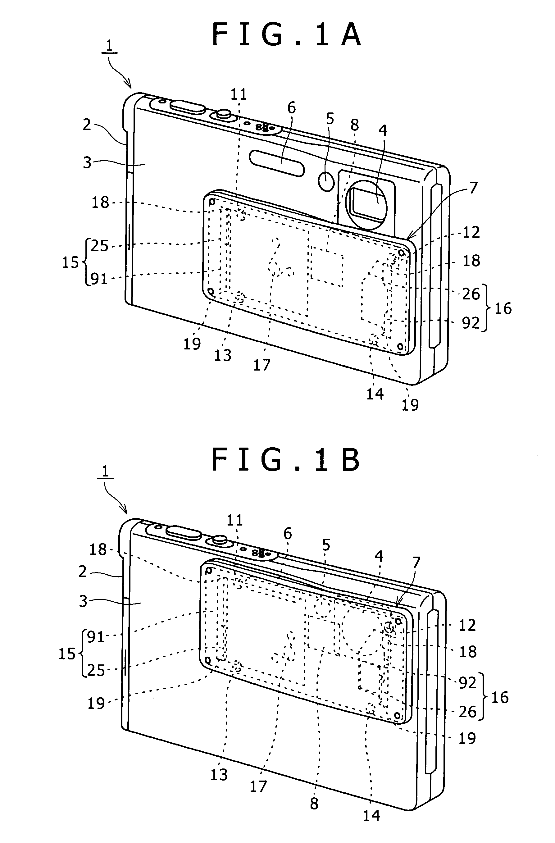
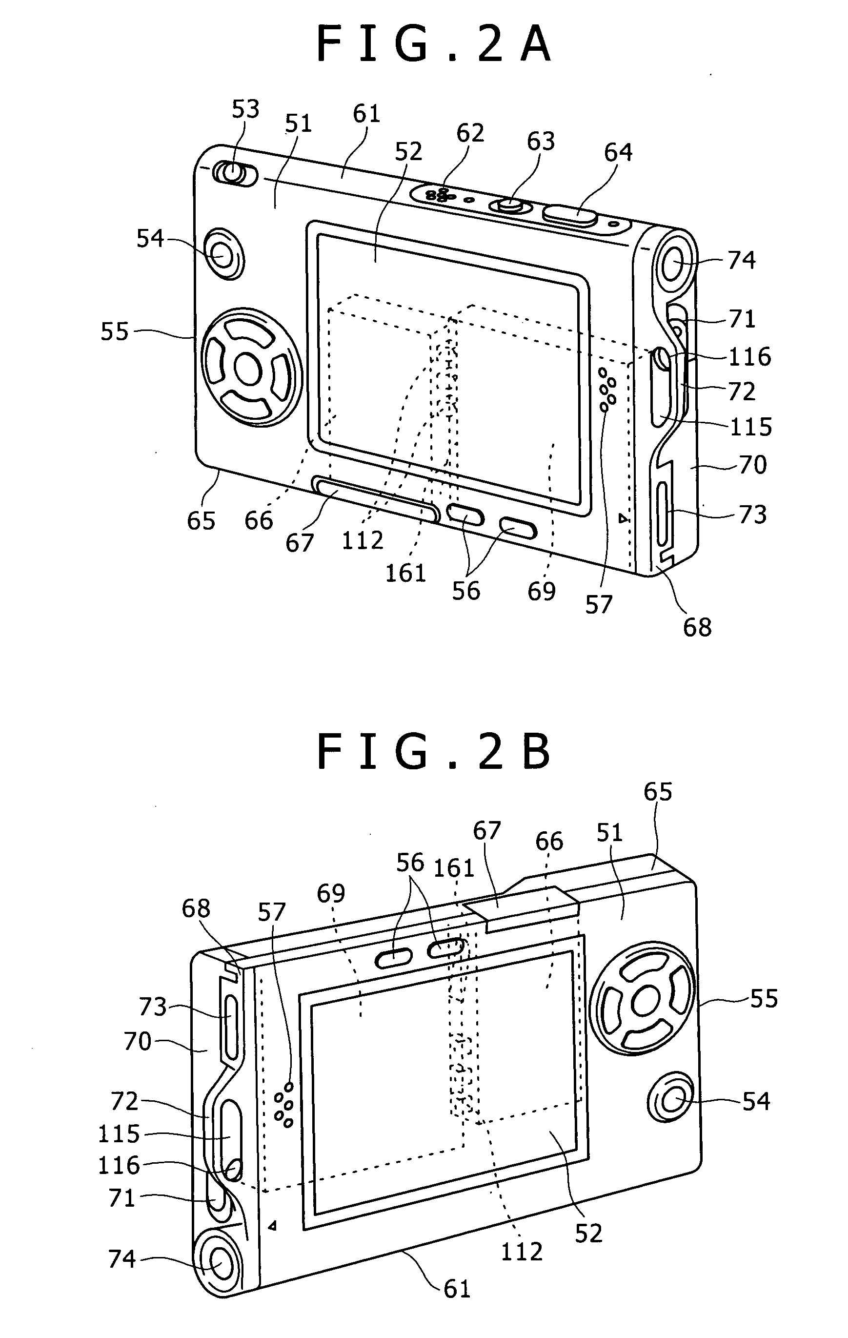
[0068]FIG. 1A and FIG. 1B are perspective views of a digital steal camera as the electronic instrument of the invention seen from a first main surface (front) side, and FIG. 2 is a perspective view of the digital steal camera of the invention seen from a second main surface (back) side.

[0069] The digital camera...


PUM


Abstract

Disclosed is an electronic instrument having a housing, a battery accommodating section provided in the housing, and a spring for battery ejection which is pressed by a battery inserted into the battery accommodating section and thus stored in power. In the instrument, the spring for battery ejection includes a spring force generation portion, a first arm portion provided at one end of the spring force generation portion, a second arm portion that is provided at the other end of the spring force generation portion and extends with a certain opening angle with respect to the first arm portion, a first shaft portion provided at an end of the first arm portion, and a second shaft portion provided at an end of the second arm portion. The first shaft portion is mounted in a first bearing portion provided in the housing, and the second shaft portion is slidably mounted in a second bearing portion provided in the housing.

Description

CROSS REFERENCES TO RELATED APPLICATIONS [0001] The present invention contains subject matter related to Japanese Patent Application JP 2005-032570 filed in the Japanese Patent Office on Feb. 9, 2005, the entire contents of which being incorporated herein by reference. BACKGROUND OF THE INVENTION [0002] 1. Field of the Invention [0003] The present invention relates to an electronic instrument using a battery as a power source. [0004] 2. Description of the Related Art [0005] As an electronic instrument including a so-called portable electronic instrument such as digital camera, an electronic instrument using a battery as a power source is known. The electronic instrument using the battery as the power source has a battery accommodating section for storing the battery in a housing, and the battery is loaded in the battery accommodating section by inserting the battery into the battery accommodating section. When the battery is charged, the battery is extracted from the battery accommo...

Claims


Application Information

Patent Timeline
Patent Type & Authority Applications(United States)
IPC IPC(8): H02J7/00
CPCH01M2/1066H01M50/209Y02E60/10H05K5/00H05K7/12
Inventor NAGANO, KOTA
Owner SONY CORP
Why Eureka
Try Eureka