Delay-based cell portion selection

a cell portion and selection technology, applied in the field of delay-based cell portion selection, can solve the problems of low capacity of proposed distributed base station concepts, increased downlink capacity automatically accompanied by a necessary similar upgrade of uplink capacity, operation and complexity, etc., to achieve the effect of reducing complexity and ensuring the separation of cell-portion specific signals

Inactive Publication Date: 2006-09-14
NOKIA CORP
View PDF5 Cites 4 Cited by
  • Summary
  • Abstract
  • Description
  • Claims
  • Application Information

AI Technical Summary

Benefits of technology

[0016] The allocating step may comprise allocating a zero amount of delay to a first cell portion and a non-zero amount of delay to a second cell portion. This means that the delay can be introduced only to some of the reception lines from the remote heads to thereby further reduce complexity. In systems with only two cell portions per distributed base station, the signals of one cell portion can be processed without any delay, while the signals of the other cell portions are delayed. The cell-portion specific amounts of delay should be set longer than propagation delay differences which result from different path lengths between the remote heads and served mobile terminals. Thereby, separation of the cell-portion specific signals can be assured.

Problems solved by technology

However, the proposed distributed base station concepts suffer from the problem of low capacity due to increased interference in uplink and shared downlink transmission power of all terminal devices or user equipments (UEs) connected wirelessly.
These concepts however lead to the disadvantage that increased downlink capacity is automatically accompanied by a necessary similar upgrade in uplink capacity, operation and complexity.

Method used


Image

  • Delay-based cell portion selection
  • Delay-based cell portion selection
  • Delay-based cell portion selection

Examples


Embodiment Construction

[0029] The preferred embodiment will now be described on the basis of a distributed base station concept in a UTRAN environment.

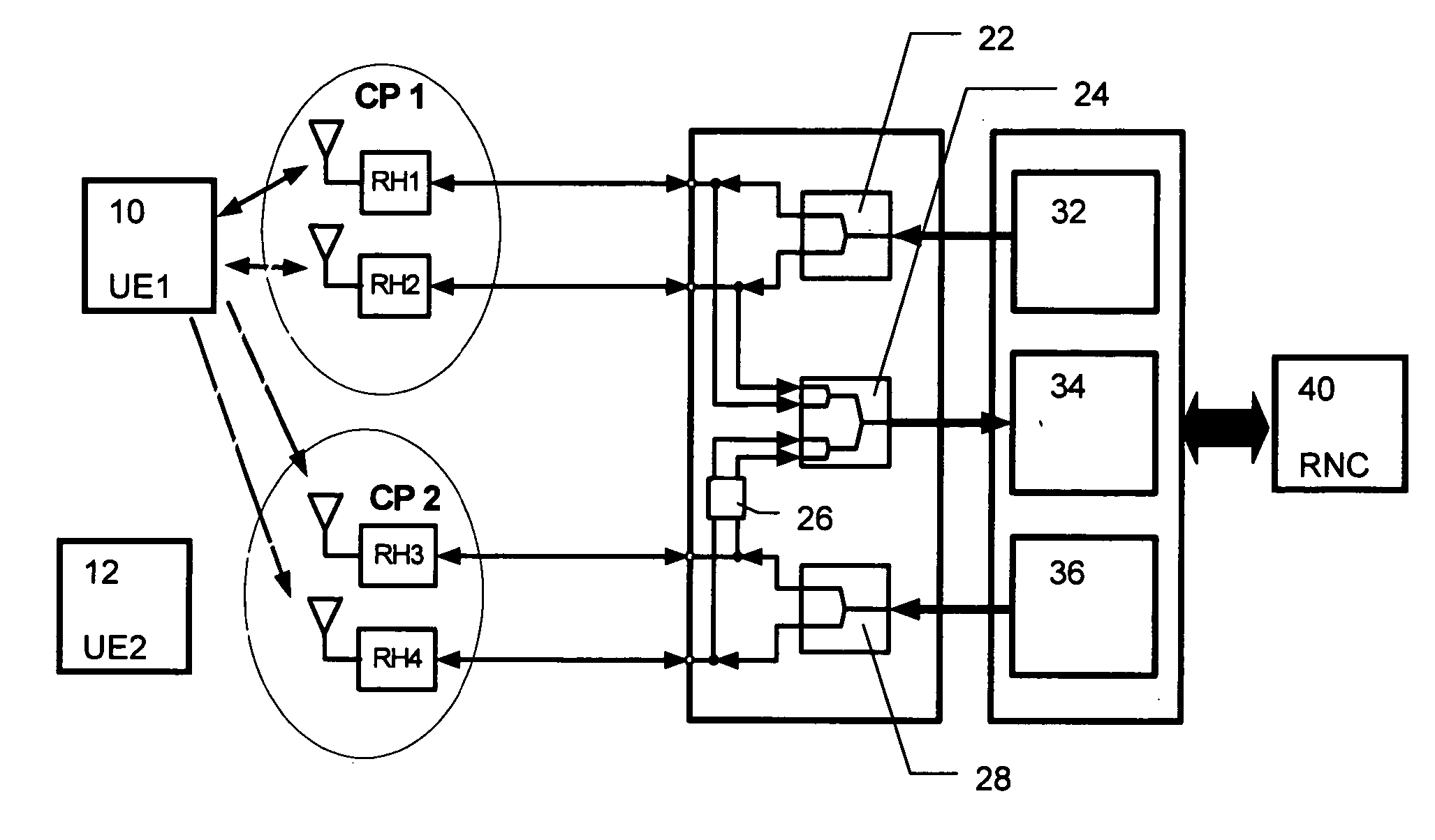
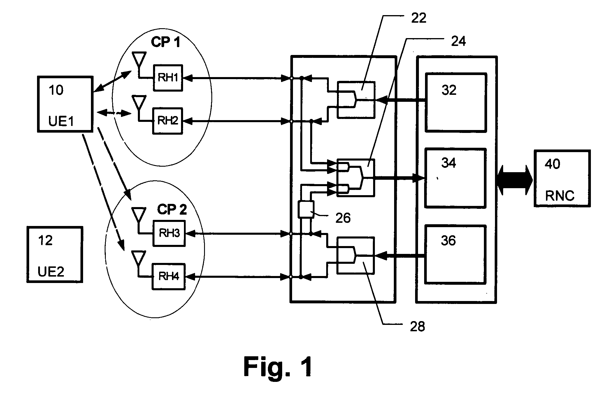
[0030]FIG. 1 shows a schematic block diagram of the first preferred embodiment, wherein a first UE 10 and a second UE 12 are connected with respective antennas of remote heads RH1 to RH4 of respective cell portions CP1 and CP2 to a splitter / combiner architecture of the distributed base station or Node B. The splitter / combiner architecture comprises two downlink splitters 22, 28, one allocated to the first cell portion CP1 with its remote heads RH1 and RH2 and the other allocated to the second cell portion CP2 with its remote heads RH3 and RH4. Thereby, an improved capacity is achieved in the downlink direction due to the fact that the two cell portions CP1 and CP2 are individually supplied by dedicated transmission signals. In the uplink direction a common combiner 24 is provided which combines all four signals received from all remote heads RH1 to RH4 of ...


PUM


Abstract

The present invention relates to a method and network device for identifying a cell portion to be selected from at least two cell portions each served by at least one respective remote head, wherein respective cell-portion specific amounts of delay are allocated to each of said at least two cell portions and signals received from said at least two cell portions are delayed by the cell-portion specific amounts of delay. Cell-portion specific signals can then be separated based on their time of occurrence. Thereby, a separation in the delay domain is possible during uplink reception in order to distinguish between different cell portions to which downlink signals can then be selectively transmitted. The downlink capacity can thus be increased without requiring increase of uplink capacity and complexity at the same time.

Description

FIELD OF THE INVENTION [0001] The present invention relates to a method and apparatus for identifying a cell portion to be selected from at least two cell portions served by at least one respective remote head of a distributed base station device, such as a Node B of an UTRAN (Universal Mobile Communications System Terrestrial Radio Access Network). BACKGROUND OF THE INVENTION [0002] With indoor coverage increasingly becoming a differentiator in office parks, shopping malls, tunnels and sports arenas, advanced indoor radio solutions have been developed in combination with high speed downlink transmission for support of bandwidth-intensive services such as video. [0003] One of the features of such improved systems is a distributed base station concept (D-BTS) where a more selective transmission is achieved by using several remote heads connected to a base station device (e.g. Node B in UTRAN). The signals from the remote heads are combined at the base station device and processed in ...

Claims


Application Information

Patent Timeline
Patent Type & Authority Applications(United States)
IPC IPC(8): H04J3/06H04Q7/24H04Q7/00H04W48/20
CPCH04W48/20
Inventor HUGL, KLAUS
Owner NOKIA CORP
Why Eureka
Try Eureka