Condensation sensor

a technology of condensation sensor and sensor body, which is applied in the field of measuring device, can solve problems such as condensation in windows

Inactive Publication Date: 2006-09-14
PREH GMBH
View PDF18 Cites 12 Cited by
  • Summary
  • Abstract
  • Description
  • Claims
  • Application Information

AI Technical Summary

Benefits of technology

[0016] Further, the merging of the measuring signals from both sensors in accordance with the present invention is particularly advantageous because only one output signal compensated by the temperature needs to be output from the sensor mo

Problems solved by technology

Further, during the automatic operation of an air-conditioning sy

Method used


Image

  • Condensation sensor
  • Condensation sensor
  • Condensation sensor

Examples


Embodiment Construction

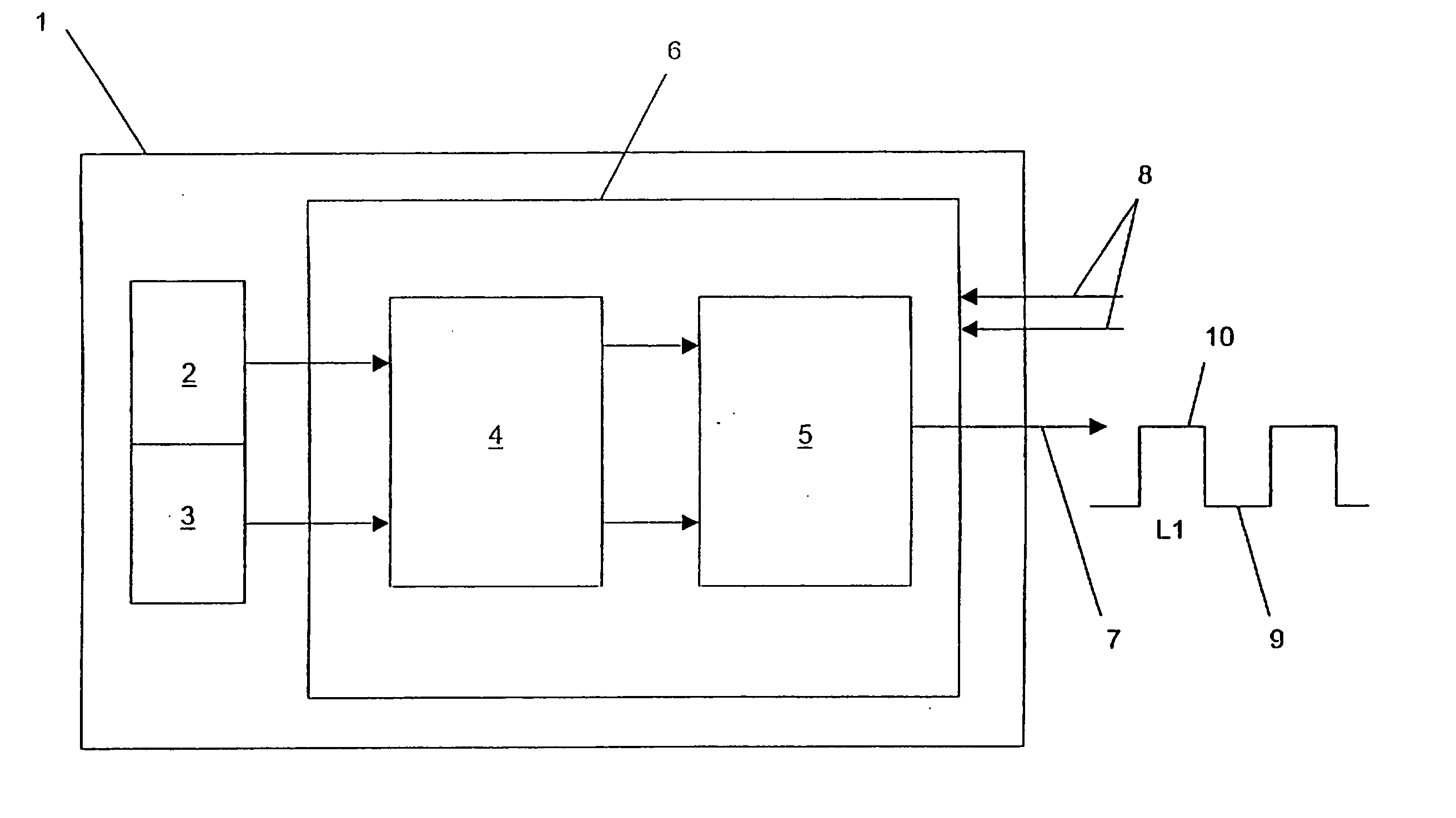
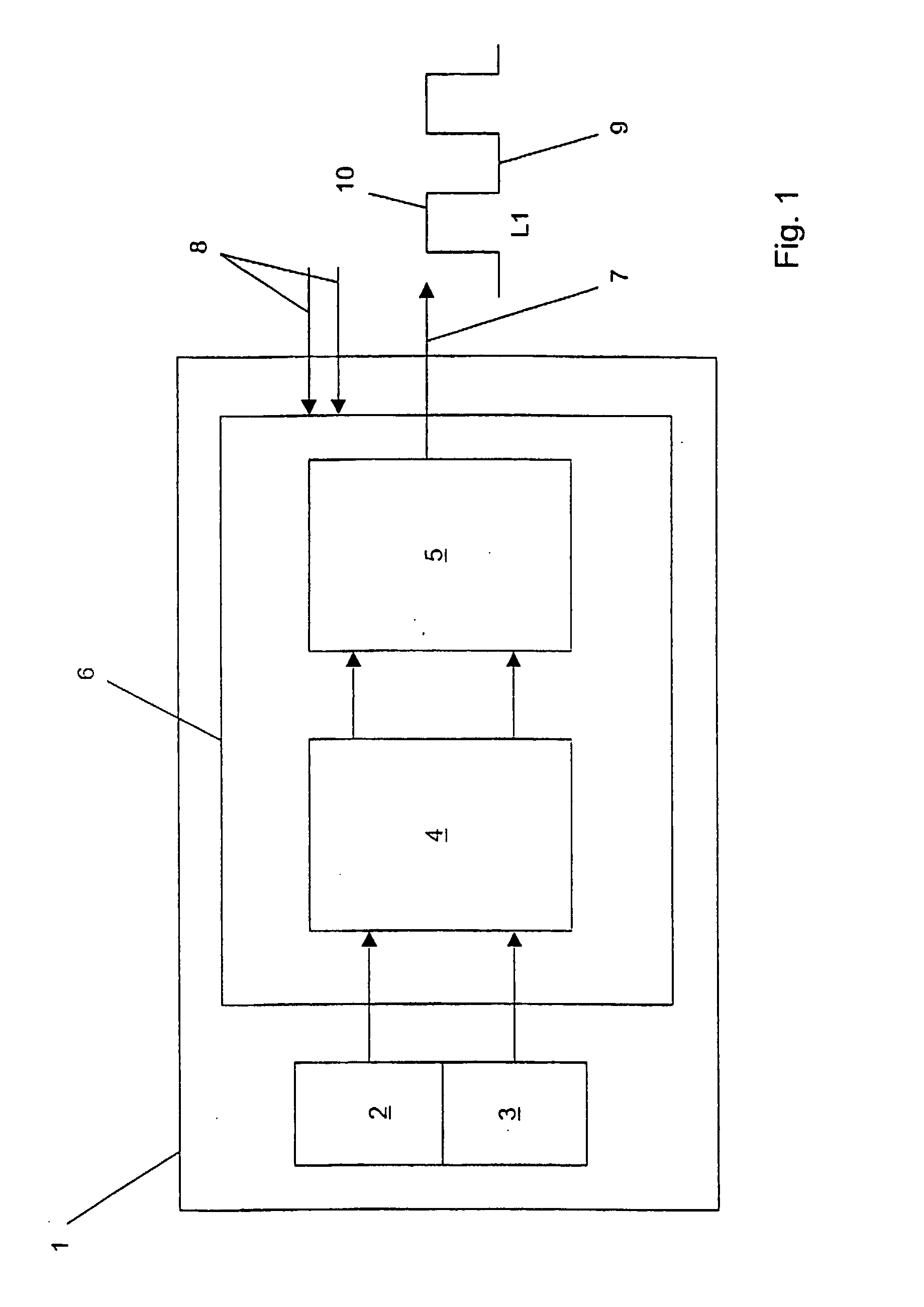
[0020] The present invention will now be described with reference to FIGS. 1 and 2. In more detail, FIG. 1 is a block diagram illustrating a sensor module 1 for measuring a humidity and temperature on a window surface. The relative humidity on the window surface is measured by a capacitive sensor 2 (moisture sensor), and the temperature of the window surface is measured by the resistor 3 (temperature sensor). Further, the resistor 3 is preferably a thermistor such as an NTC resistor.

[0021] In addition, the moisture sensor 2 and the temperature sensor 3 are glued directly to the windshield (not shown) via a thermally conductive film, whereby in one embodiment of the present invention, the sensor module 1 is placed as an entire unit directly on the window surface. Alternatively, the sensor module 1 can also be integrated into a rearview mirror placed on the windshield.

[0022] Further, as shown in FIG. 1, the sensor module 1 also include an oscillator 4 (e.g., an RC oscillator) connec...


PUM


Abstract

A measuring device for detecting a humidity and temperature of a window surface including at least one moisture sensor and at least one temperature sensor placed on the window surface, an evaluation unit connected downstream from the moisture and temperature sensors, and a signal converting and linking unit placed between the moisture and temperature sensors and the evaluation unit. Further, when the temperature sensor detects a change in a temperature of the window surface or the moisture sensor detects a change in a moisture of the window surface, a frequency of an oscillator included in the signal and converting unit is changed.

Description

[0001] This non-provisional application is a continuation application of PCT / EP2004 / 009986, which was filed on Sep. 8, 2004, and which claims priority to German Patent Application No. DE 103 42 333.8, which was filed in Germany on Sep. 11, 2003, and which are both herein incorporated by reference.BACKGROUND OF THE INVENTION [0002] 1. Field of the Invention [0003] The invention relates to a measuring device for detecting the humidity and temperature of a window surface facing a vehicle interior, particularly of a vehicle windshield including at least one capacitive moisture sensor and at least one temperature sensor, which are placed together on the window surface, and a downstream evaluation unit. Further, measuring signals from the moisture and temperature sensors are combined into a single signal, and affect the shape of the single signal. [0004] 2. Description of the Background Art [0005] Heating and air-conditioning systems provide a high level of interior comfort to passengers ...

Claims


Application Information

Patent Timeline
IPC IPC(8): G01K1/14G01K7/00G01N25/02B60H1/00
CPCB60H1/00785
Inventor RUTTIGER, ANTONPESCHEL, MARKUS
Owner PREH GMBH
Why Eureka
Try Eureka