Systems, methods and apparatus for filtered back-projection reconstruction in digital tomosynthesis

Active Publication Date: 2006-09-14
GENERAL ELECTRIC CO
View PDF8 Cites 39 Cited by
  • Summary
  • Abstract
  • Description
  • Claims
  • Application Information

AI Technical Summary

Problems solved by technology

The images of structures outside the tomosynthesis plane do not overlap exactly, resulting in a depth dependent blurring of these structures.
But these methods are known to produce “streaking artifacts.”
Unfortunately, conventional filtered back-projection methods suffer from artifacts generated in the 3-D image

Method used


Image

  • Systems, methods and apparatus for filtered back-projection reconstruction in digital tomosynthesis
  • Systems, methods and apparatus for filtered back-projection reconstruction in digital tomosynthesis
  • Systems, methods and apparatus for filtered back-projection reconstruction in digital tomosynthesis

Examples


an embodiment

METHODS OF AN EMBODIMENT

[0038] In the previous section, a system level overview of the operation of an embodiment is described. In this section, the particular methods of such an embodiment are described by reference to a series of flowcharts. Describing the methods by reference to a flowchart enables one skilled in the art to develop such programs, firmware, or hardware, including such instructions to carry out the methods on suitable computers, executing the instructions from computer-readable media. Similarly, the methods performed by the server computer programs, firmware, or hardware are also composed of computer-executable instructions. Methods 200-700 are performed by a program executing on, or performed by firmware or hardware that is a part of, a computer, such as computer 802 in FIG. 8.

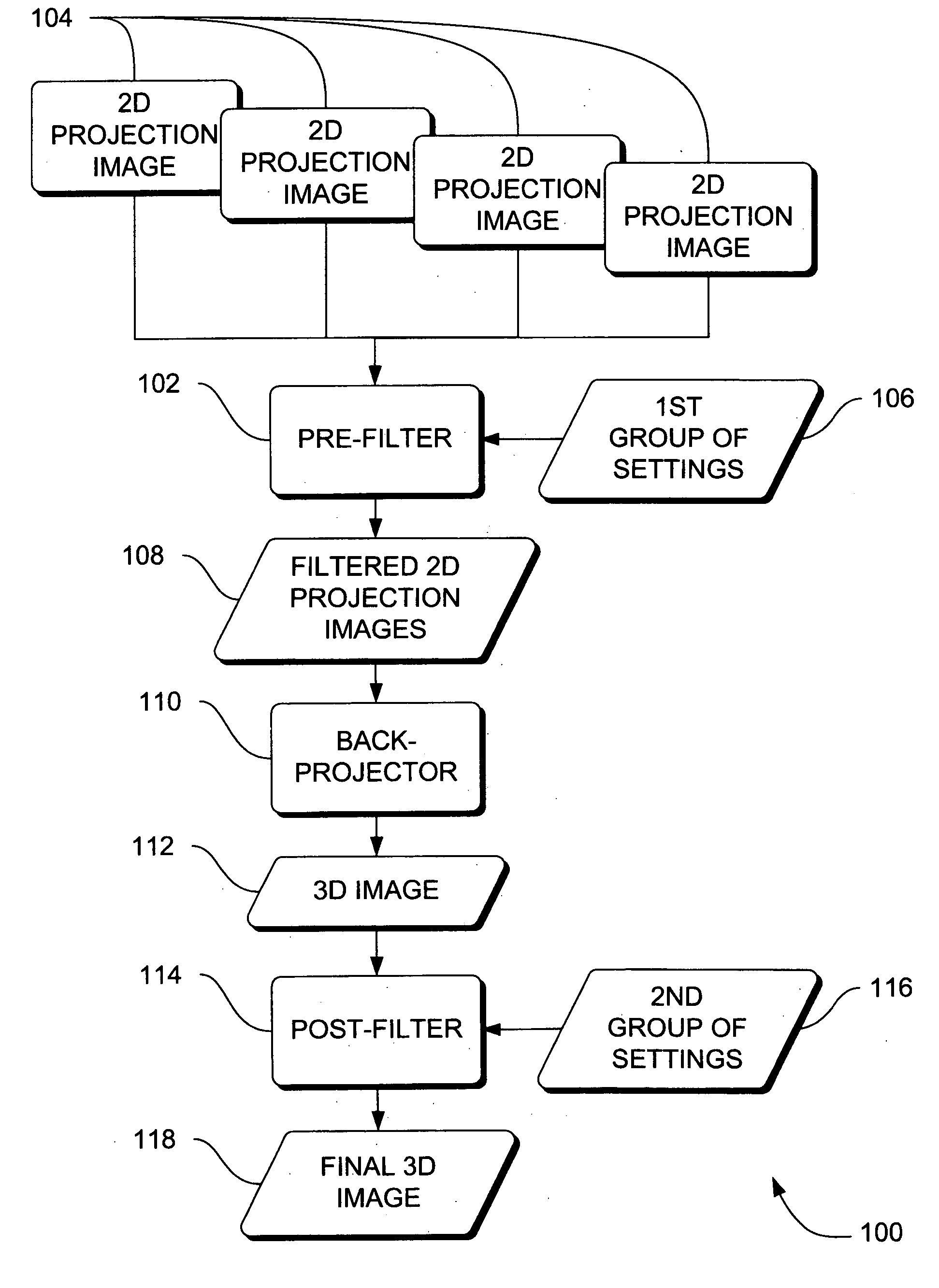
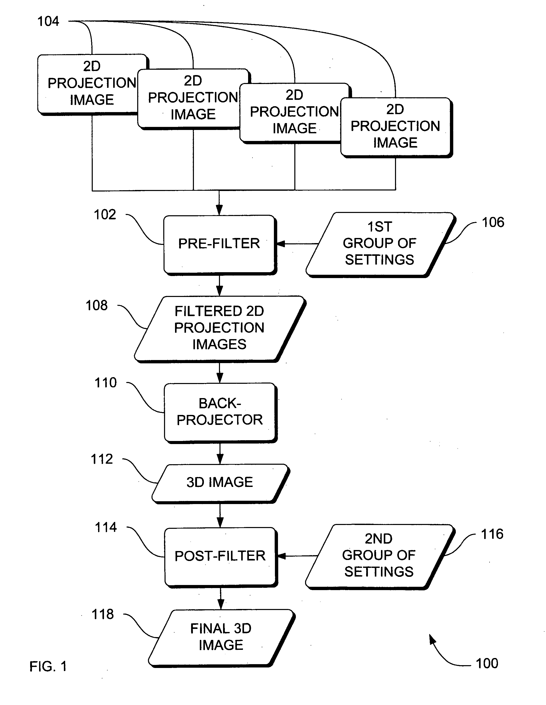
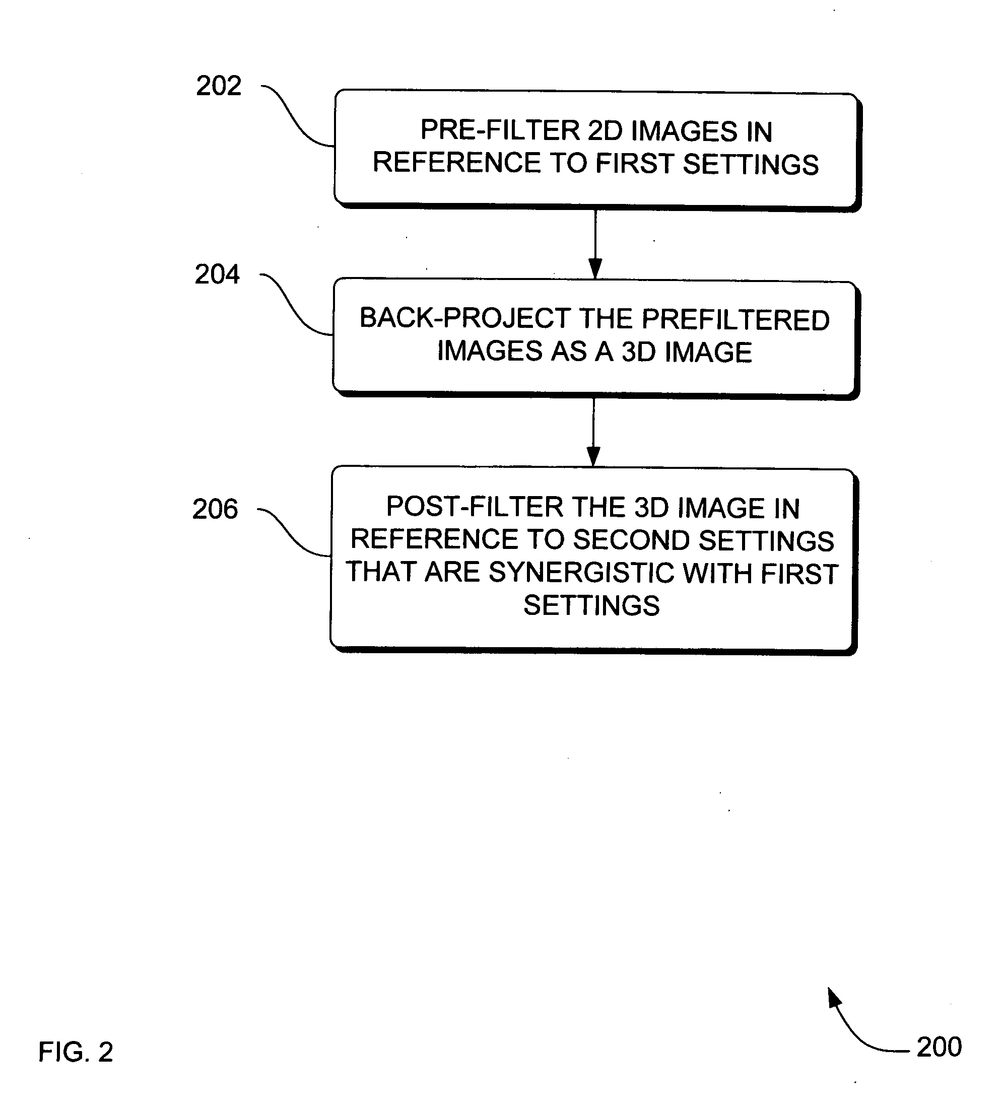
[0039]FIG. 2 is a flowchart of a method 200 to construct a three-dimensional (3-D ) image of an object from a plurality of two-dimensional (2-D) projection images of the object according to...


PUM


Abstract

Systems, methods and apparatus are provided through which a specialized back-projection process reconstructs a finely detailed and crisp three-dimensional image (3-D ) from a series of two-dimensional (2-D) images by pre-filtering the 2-D images with a first group of settings before back-projecting the 2-D images into a 3-D image, and then post-filtering the 3-D image with another group of settings. In some embodiments, the first group of settings and the second group of settings are synergistically optimized in relation to each other to provide emphasis on a structure of interest in the object.

Description

RELATED APPLICATION [0001] This invention relates generally to medical imaging, and more particularly to configuration of medical image processing. BACKGROUND OF THE INVENTION [0002] Electromagnetic imaging is typically used to inquire into the condition of a particular structure of interest in an object. Structures of interest in a human subject include a particular organ such as the heart, and a particular bone such as the tibia. [0003] Digital tomosynthesis imaging further provides a three dimensional (3-D) image of an object that is reconstructed from a set of two-dimensional (2-D) projection radiograph images. A digital tomosynthesis system includes an X-Ray source and a 2-D X-Ray detector, which is a digital detector. In conventional digital tomosynthesis systems, during data acquisition the X-Ray source is rotated by a gantry on an arc through a limited angular range about a pivot point and a set of projection radiographs of the object are acquired by the detector at discrete...

Claims


Application Information

Patent Timeline
IPC IPC(8): G06K9/00G01C3/14H04N13/00G06K9/36G06T15/00A61B6/02G06T1/00
CPCG06T11/005G06T11/006G06T11/008G06T2211/421G06T2211/436Y10S128/922
Inventor AVINASH, GOPAL B.LI, BAOJUNUPPALURI, RENUKA
Owner GENERAL ELECTRIC CO
Why Eureka
Try Eureka