
Orthodontic correction device

a technology for orthodontics and clamps, applied in the field of orthodontics, can solve the problems of affecting the quality of orthodontics, and releasing binding, and achieve the effect of simple manufacturing

Inactive Publication Date: 2006-09-14
CLOR CHARLES
View PDF2 Cites 16 Cited by
  • Summary
  • Abstract
  • Description
  • Claims
  • Application Information

AI Technical Summary

Benefits of technology

[0014] The purpose of the invention is to cope with the drawbacks of the state of technique while omitting the use of a rubber band or a metal wire as well as of a removable member. Moreover, the orthodontic device according to the invention remains simple to be manufactured and cheaper.
[0020] According to another additional feature of the device according to the invention, the lower face of the pin has a slope, so that its end is closer to the bottom of the groove, so as to increase the hold of the arch in said groove.

Problems solved by technology

The problem experienced with such a device resides in maintaining the arch in the groove of each bracket so as to prevent it from being released from it.
However, a drawback resides in that the binding can be released, in particular when brushing the teeth, and may eventually damage the gum in the case of the metal wire, or may even be swallowed.
The rubber bands lose their quality quickly and become dirty depending on the saliva and on the food habits, resulting into an even less aesthetic aspect of the bracket, and it is thus necessary to change them regularly.
A device comprising a removable part articulated through a hinge has the drawback of being complex as regards the manufacture of the bracket.
Moreover, the hinge is fitted on an axis or a pivot likely to be released or even to break.
Even though this type of device does not use an elastic or metal binding, it has however the drawback of having a removable member having the above-mentioned drawbacks, in particular, it is likely to be released.

Method used


Image

  • Orthodontic correction device
  • Orthodontic correction device
  • Orthodontic correction device

Examples

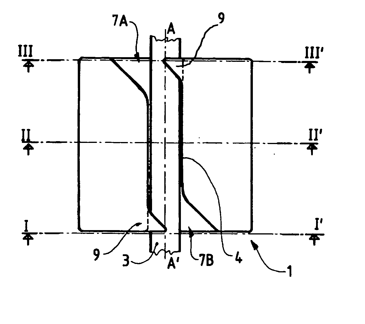
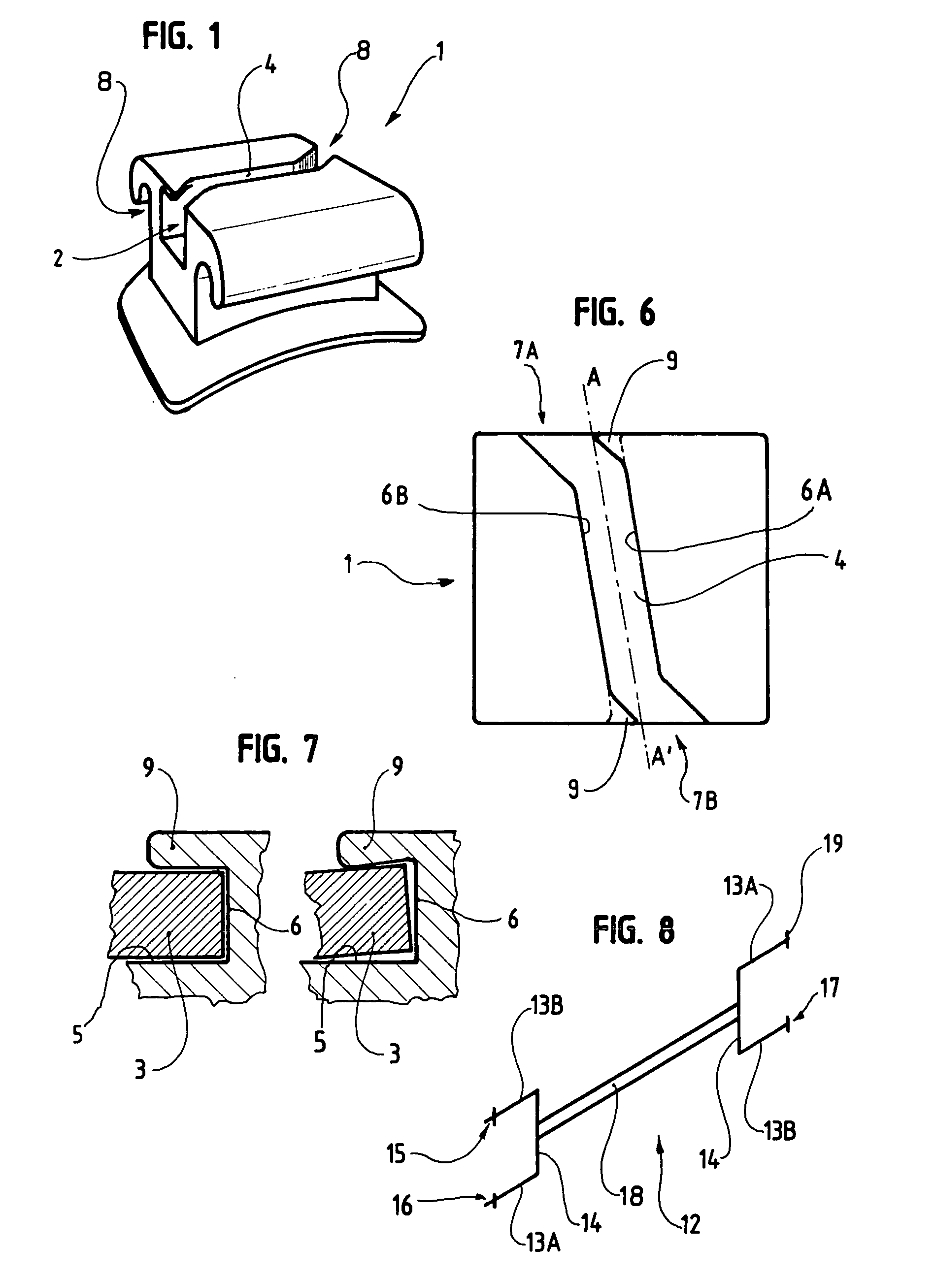
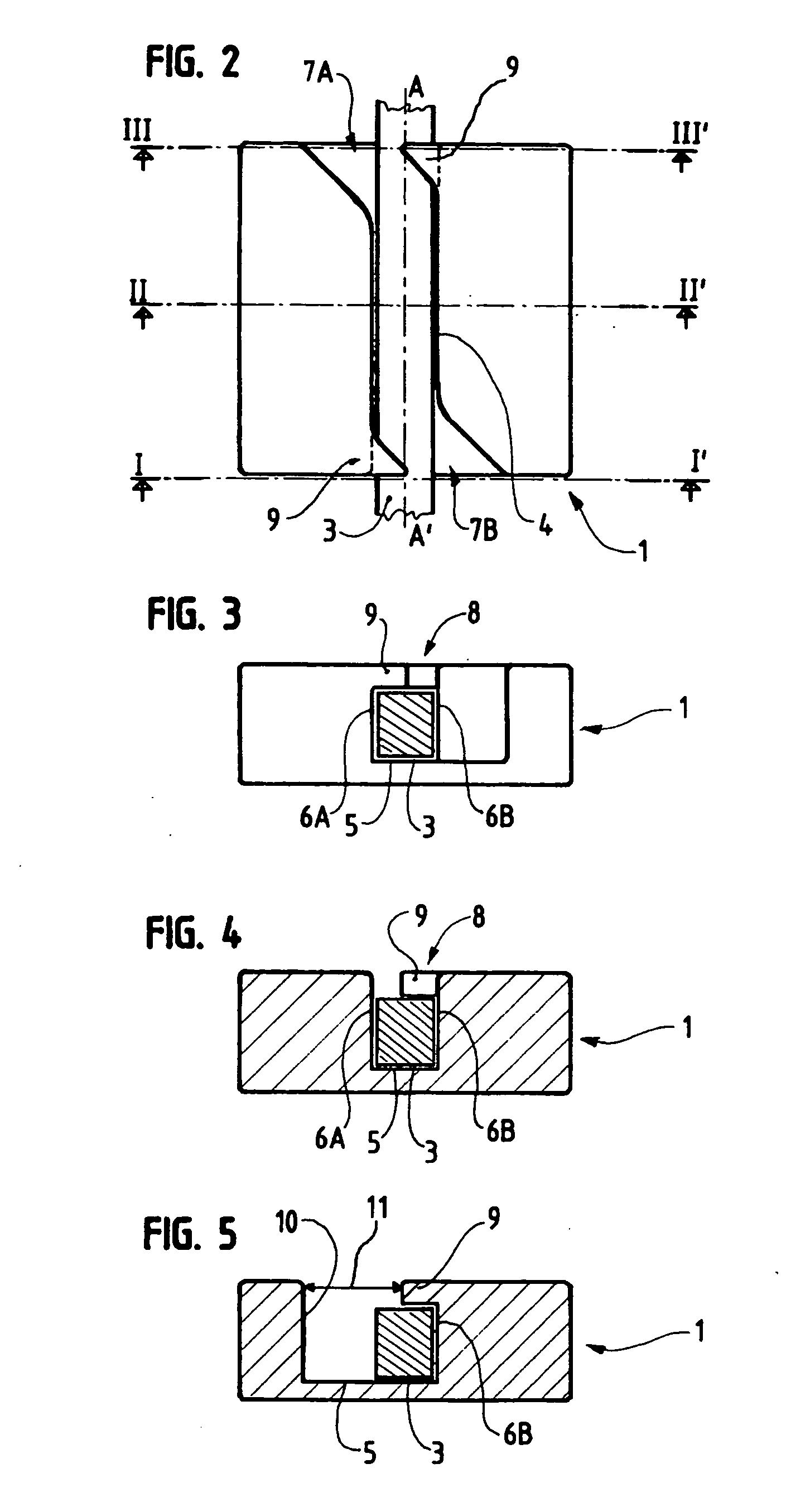

Embodiment Construction

[0033] The present invention relates to an orthodontic correction device 1, in particular a tooth-alignment correction device.

[0034] Such an orthodontic correction device 1 is commonly in the form of means for locking an arch 3, such as a bracket, as can be seen in FIG. 1, and aimed at being fixed through gluing to the front or back face of a tooth.

[0035] This bracket comprises means 2 capable of accommodating the arch 3, such as a groove 4 passing through the bracket. In particular, the arch 3, once it has been placed, rests on the bottom of the groove 4. The latter is delimited by a bottom 5 and two longitudinal edges 6A and 6B. It extends longitudinally with respect to the bracket, from an end 7A to an end 7B, the arch 3 emerging through each one of the ends 7A and 7B.

[0036] In this respect, the arch 3 is made of a metal wire having elastic shape-memory characteristics. It can have a round, square or rectangular cross-section, so that it acts on the bottom 5 and the edges 6 of...


PUM


Abstract

Orthodontic correction device includes a locking device for an arch in the form of a bracket in which is provided for a groove aimed at co-operating with the arch. The groove includes a blocking device for the arch in the form of at least one pin extending at least partly above the groove at the level of the opening of the said groove. The opening is shaped so as to allow, during the insertion of the arch into the groove, passing around the pin.

Description

RELATED U.S. APPLICATIONS [0001] Not applicable. STATEMENT REGARDING FEDERALLY SPONSORED RESEARCH OR DEVELOPMENT [0002] Not applicable. REFERENCE TO MICROFICHE APPENDIX [0003] Not applicable. FIELD OF THE INVENTION [0004] The present invention is related to the field of orthodontics, in particular to the field of the orthodontic clamps, commonly referred to as brackets. BACKGROUND OF THE INVENTION [0005] The orthodontic clamps or brackets are used in orthodontics in tooth-alignment correction devices. A bracket is an element aimed at being fixed through gluing to the front face, and sometimes to the back face, of each tooth, in order to serve as a clamp for an arch. This arch is usually rigid or shape memorizing, made out of metal. This arch is fixed to each bracket, generally at the level of a groove provided for in the latter. The cross-section of this arch can be designed round, square or rectangular. [0006] The problem experienced with such a device resides in maintaining the ar...

Claims


Application Information

Patent Timeline
IPC IPC(8): A61C3/00
CPCA61C7/28A61C7/02
Inventor CLOR, CHARLES
Owner CLOR CHARLES
Learn More