
Systems and methods for frequency reuse in wireless networks

a wireless network and frequency reuse technology, applied in wireless communication, sustainable buildings, high-level techniques, etc., can solve the problems of low snr and correspondingly low data rates, limiting factors of spectral efficiency, and reducing data rates in these areas. achieve the effect of reducing interference and high spectral efficiency

Active Publication Date: 2006-09-14
NEXTEL COMMUNICATIONS
View PDF11 Cites 9 Cited by
  • Summary
  • Abstract
  • Description
  • Claims
  • Application Information

AI Technical Summary

Benefits of technology

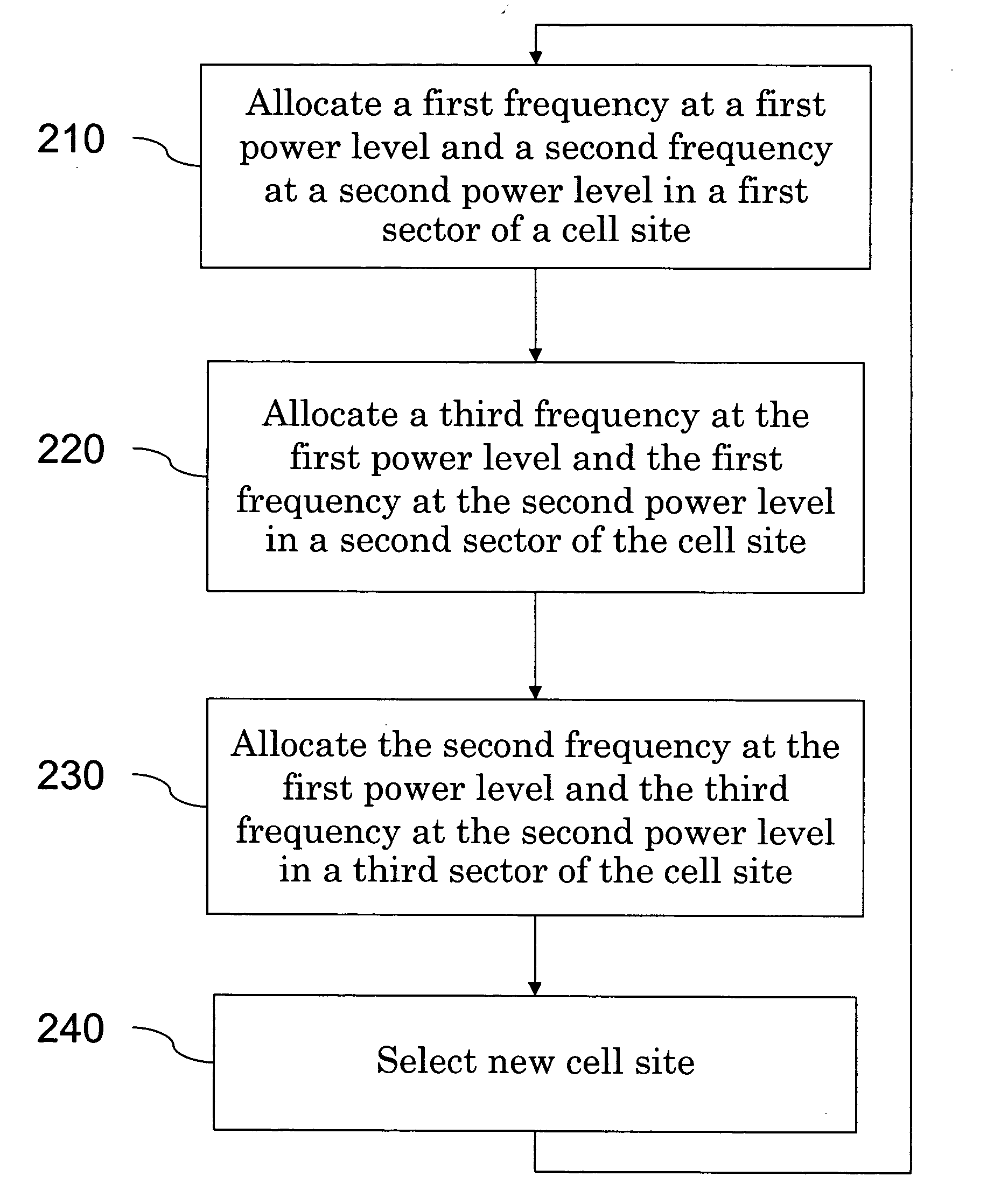
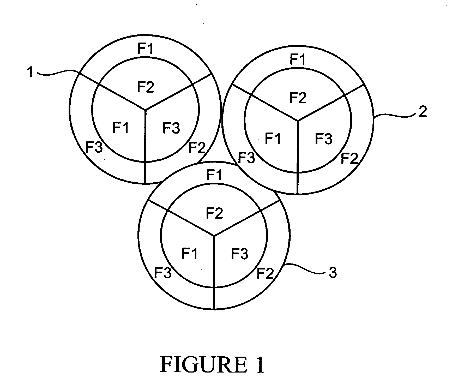
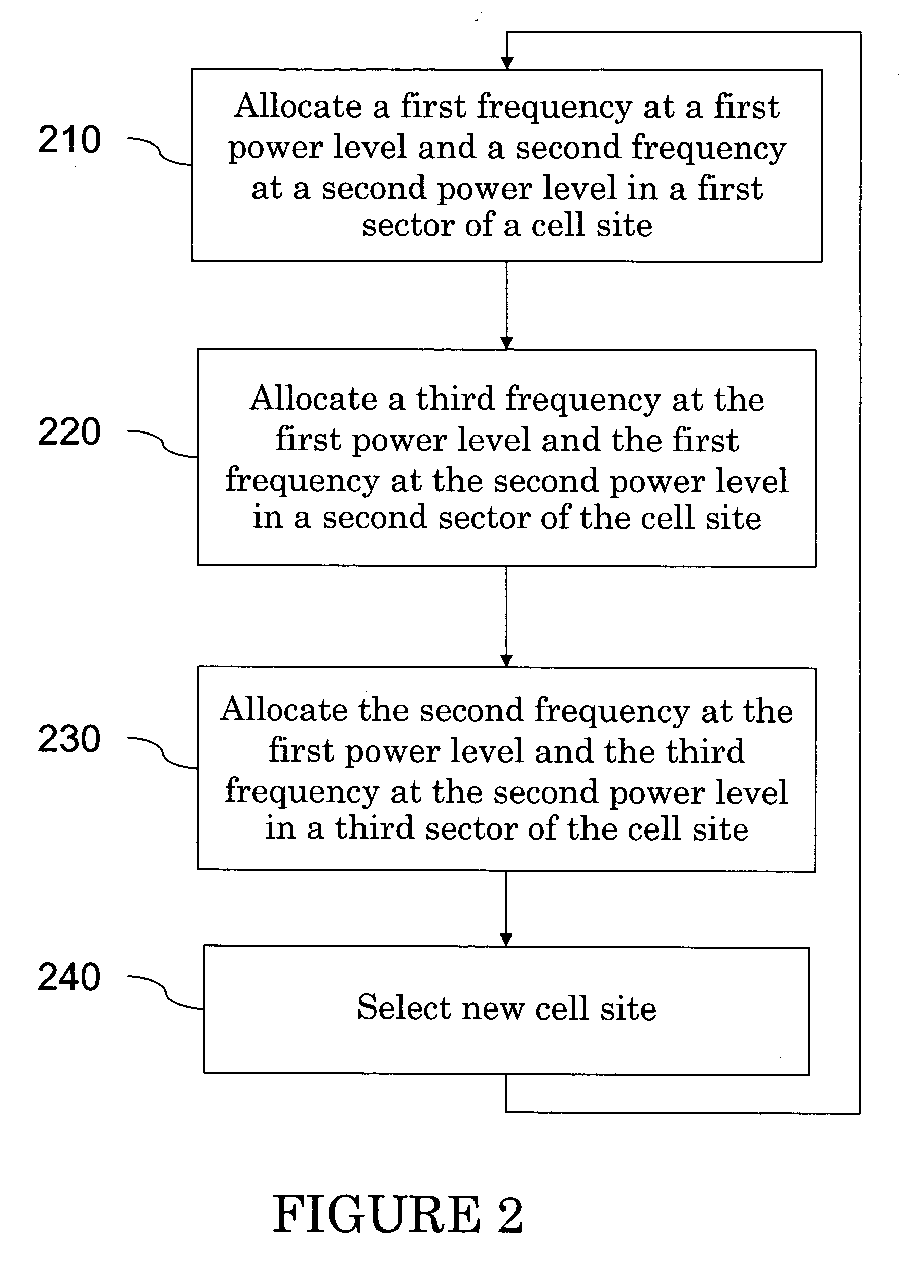
[0009] The present invention overcomes the above-identified and other deficiencies of prior frequency reuse schemes by providing high spectral efficiency and reduced interference in areas where cell sites overlap. Specifically, the present invention provides three or more frequencies per cell site, with each sector employing two frequencies, one frequency being transmitted at a higher power and the second frequency being transmitted at a lower power. The higher power frequency in one sector differs from the higher power frequency employed in the other two sectors, and the lower power frequency used in one sector differs from the lower power frequency used in the other two sectors.

Problems solved by technology

One limiting factor on spectral efficiency is signal-to-noise ratio (SNR).
However, this also results in considerable interference in areas where cells overlap, which reduces data rates in these areas.
Universal frequency reuse technologies experience an equal-power boundary in between two sectors, thereby resulting in a low SNR and correspondingly low data rates even when wireless devices are geographically close to the base station.
These areas of high interference reduce data rates in a significant portion of the wireless data network coverage area, thereby impacting the end user data experience.
Although this technique improves the SNR in areas where cell boundaries overlap, spectral efficiency is reduced compared to the universal frequency reuse because frequencies are used only ⅓ as often.
However, near the center of the cell site, this results in the third, lowest power carrier experiencing average SNR levels several dBs worse than the SNR provided by the two higher-power carriers.
Additionally, wireless devices near the center of the cell site are forced to be served on the lowest-power carrier, which degrades the overall sector throughput.

Method used


Image

  • Systems and methods for frequency reuse in wireless networks
  • Systems and methods for frequency reuse in wireless networks
  • Systems and methods for frequency reuse in wireless networks

Examples


Embodiment Construction

[0014] As illustrated in FIG. 1, in accordance with exemplary embodiments of the present invention, each cell site is allocated three frequencies, F1, F2 and F3. It should be recognized that as used herein, the term frequency can refer to a single frequency or a number of frequencies constituting a frequency band. The frequencies which are illustrated as providing coverage to the inner portions of the cell site are the lower power frequencies, while those illustrated as providing coverage at the outer portions of the cell site are the higher power frequencies. The difference in power levels between the high and low power frequencies can be, for example, 6 dB. However, depending upon implementation the difference in power levels can be greater than or less than 6 dB. As illustrated in FIG. 1, in cell 1, frequency F1 is transmitted at a higher power in a first sector and at a lower power in a second sector; frequency F2 is transmitted at a higher power in a third sector and at a lower...


PUM


Abstract

A frequency reuse scheme that provides high spectral efficiency and reduced interference in areas where cell sites overlap is provided. Three frequencies are allocated per cell site, with each sector employing two frequencies, one frequency being transmitted at a higher power and the second frequency being transmitted at a lower power. The higher power frequency in one sector differs from the higher power frequency employed in the other two sectors, and the lower power frequency used in one sector differs from the lower power frequency used in the other two sectors.

Description

[0001] The present application claims priority under 35 U.S.C. § 119 to U.S. Provisional Patent Application No. 60 / 661,025, filed Mar. 14, 2005, the entire disclosure of which is herein expressly incorporated by reference.BACKGROUND OF THE INVENTION [0002] Wireless networks, such as cellular networks, typically employ radio frequency spectrum allocated by governmental bodies. Governmental bodies allocate the radio frequency spectrum between a number of wireless network operators. Additionally, only certain portions of the radio frequency spectrum is useable for wireless networks. Accordingly, radio frequency spectrum is a scarce and valuable resource that needs to be used as efficiently as possible, which is commonly referred to as spectral efficiency. In cellular networks, frequency reuse, i.e., how often frequencies are reused in different cell sites, is a common measure of spectral efficiency. [0003] One limiting factor on spectral efficiency is signal-to-noise ratio (SNR). Wirel...

Claims


Application Information

Patent Timeline
IPC IPC(8): H04Q7/20H04W16/00
CPCH04W16/00Y02B60/50Y02D30/70
Inventor HYSLOP, DOUGLAS A.STARZEC, MATTHEWTHAKORE, UDIT
Owner NEXTEL COMMUNICATIONS
Learn More