
Urinary flow control device & method

a control device and urinary flow technology, applied in the field of medical devices, can solve the problems of inconvenient device components, inconvenient treatment, persistent urinary incontinence for both men and women,

Active Publication Date: 2006-09-14
SRS MEDICAL SYST INC
View PDF3 Cites 7 Cited by
  • Summary
  • Abstract
  • Description
  • Claims
  • Application Information

AI Technical Summary

Benefits of technology

"The invention is a urinary flow control device that is placed in the bladder to control the flow of urine. The device has a bladder-responsive flow control assembly that is sealed from the urine to prevent damage from the corrosive environment of the bladder and ureter. The device can be unlatched and reset for further use. It also has a magnetic latching function that allows for controlled passage of urine from the bladder to the ureter. The device can be used to control urinary flow in patients with bladder control issues. It provides over-pressure protection and allows for limited displacement of the fluid control assembly components at discrete predetermined pressures or pressure ranges. The device can be configured with features of co-pending applications."

Problems solved by technology

Although a variety of treatment devices and / or methodologies have been developed, urinary incontinence for both men and women remains a persistent problem.
As circumstances warrant, the wearing of special fluid retaining pants has been an option, all be it an undesirable one, for both social and practical reasons.
Remedial approaches are almost always less attractive than corrective approaches, which generally require the placement or implantation of an indwelling device within the urethra.
Some of the problems and disadvantages of known devices include the deleterious effects (i.e., pitting, depositions, etc.) associated with the urethral environment upon critical device components (e.g., valve actuators, flow conduits, etc.) which at a minimum render such devices less effective, and which at a maximum, cause device component failure or render the device wholly ineffective, which necessitates emergent removal and, as the case may be, urinary tract damage repair.
Problems of device leakage, or less than complete emptying of the bladder are also widely known.
Furthermore, issues surrounding device deployment and fit, positioning, repositioning, and retention (i.e., sufficient anchoring) have also been well documented.
Second, physical straining due to lifting, laughing, coughing, and other “exertions” may produce inter-abdominal forces on the bladder, which may translate to pressures in excess of 40 cm H2O for a short time interval or duration.
Based upon clinical findings, many have been shown to be uncomfortable, thus severely retarding their utility as a therapy.
Fifth, flow control devices must have longevity of operation.
Working components that are exposed to urine are susceptible to encrustation, which may compromise device operation and thereby place a wearer at risk of injury or even death.
This is exceedingly important for a male due to the more difficult, and more inconvenient, removal associated with typical flow control devices.

Method used


Image

  • Urinary flow control device & method
  • Urinary flow control device & method
  • Urinary flow control device & method

Examples


Embodiment Construction

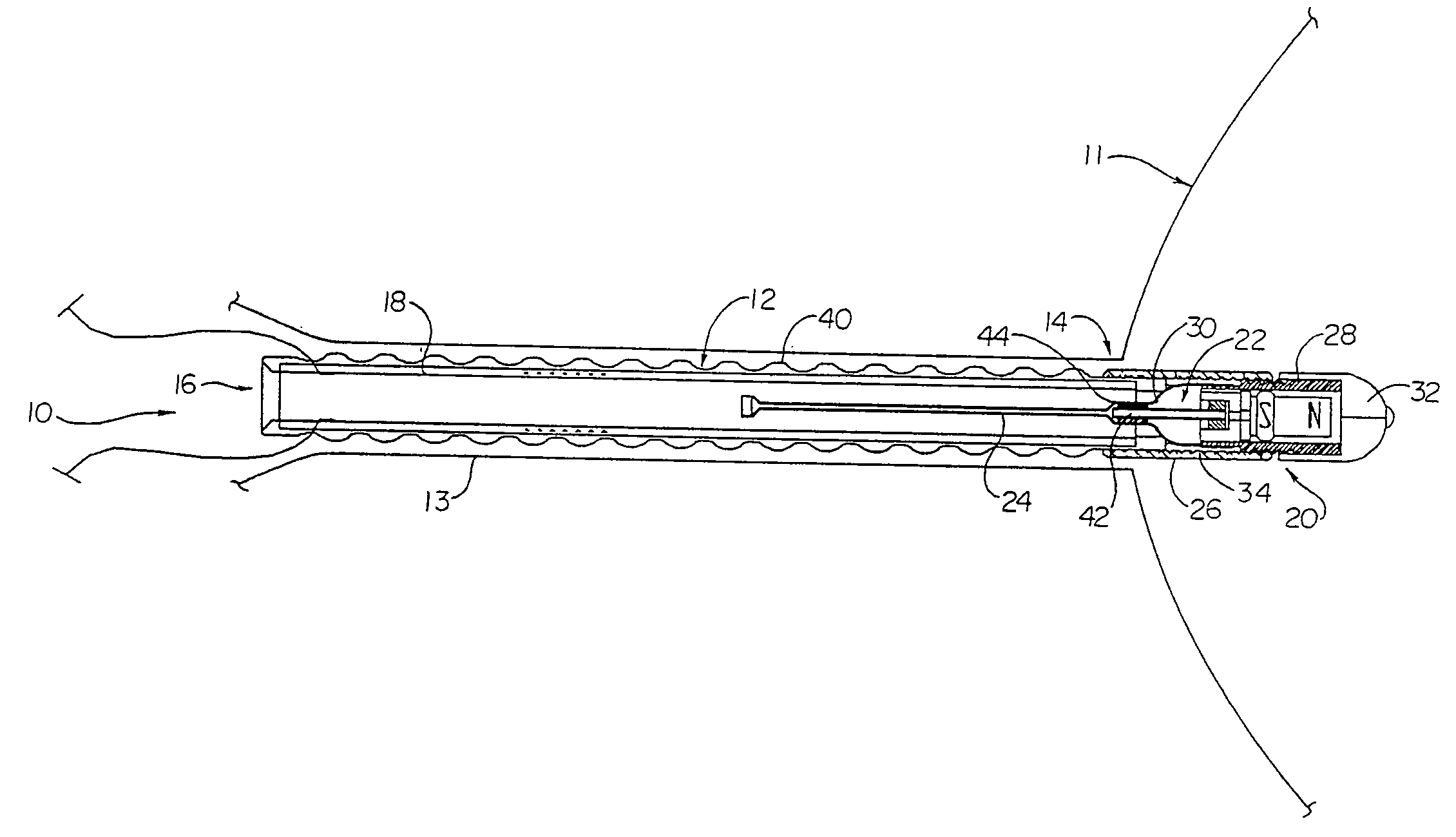
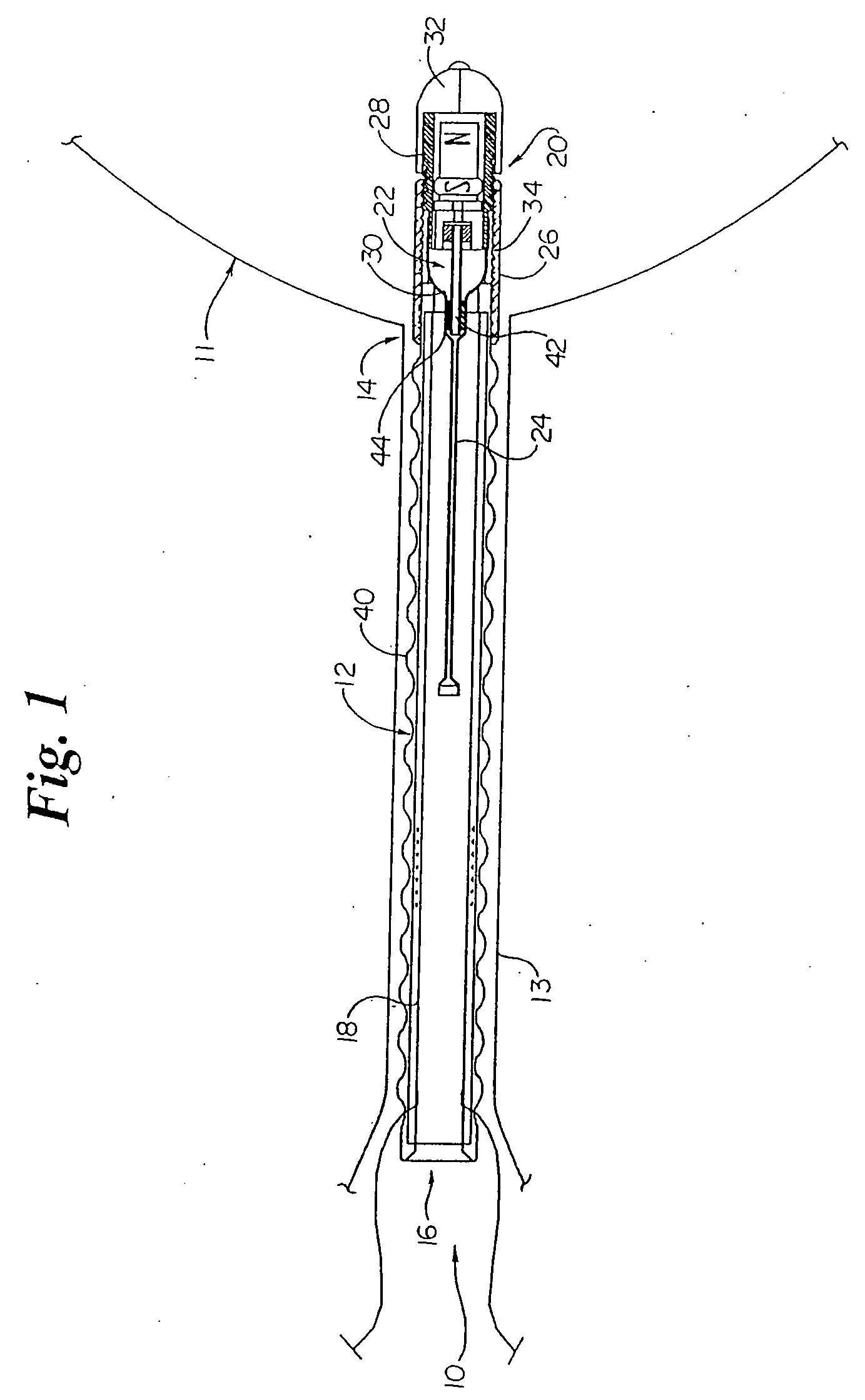
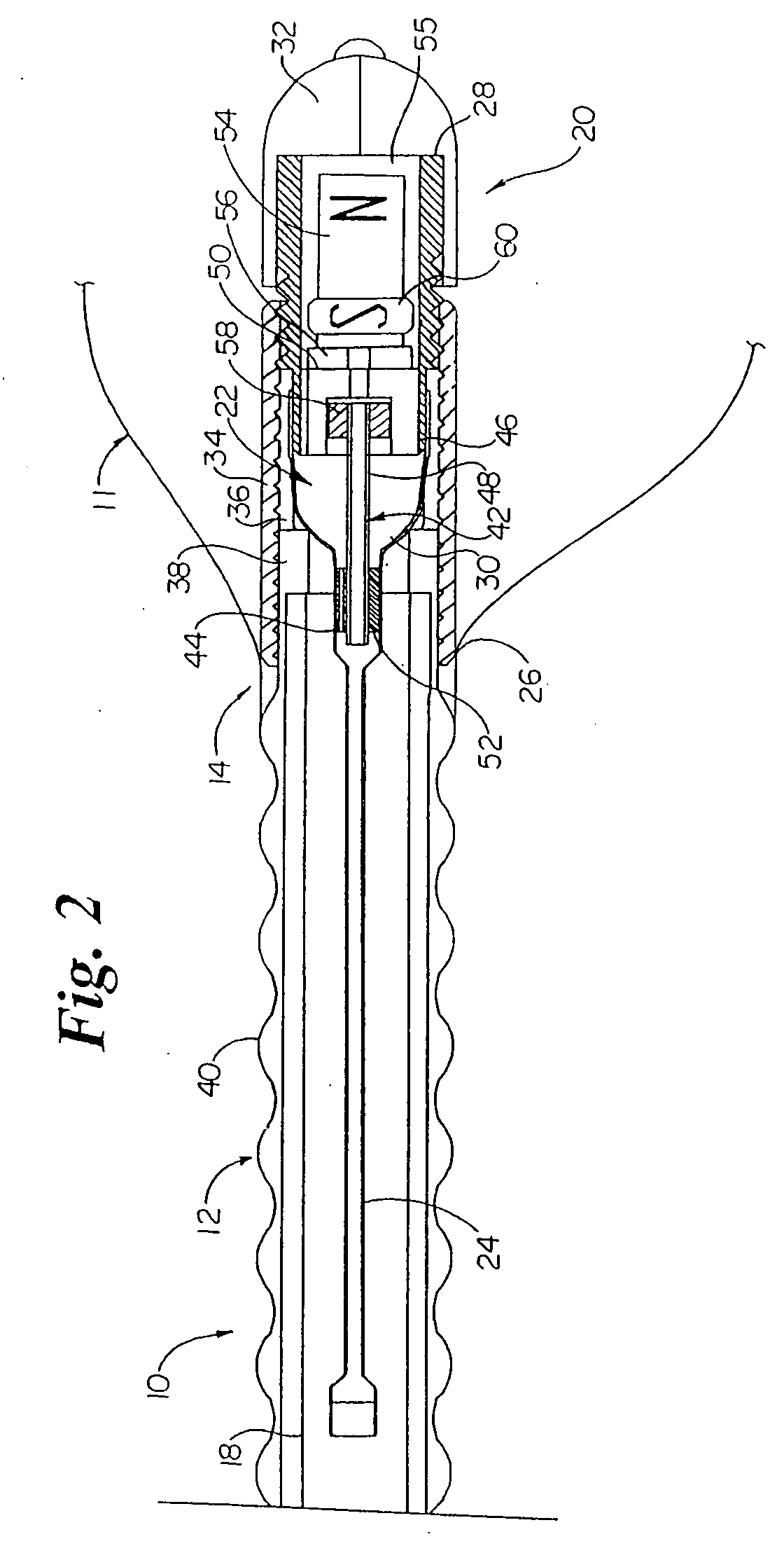
[0032] Generally referencing the figures, more particularly to FIGS. 1 and 2, there is shown a urinary flow control device 10 which generally includes an elongate member 12 having proximal 14 and distal 16 ends and a lumen 18 capable of discharging urine therethrough, and a flow control assembly 20, operatively joined to the elongate member 12, having first 22 and second 24 fluid containing compartments adapted to be in fluid communication with each other. The flow control assembly 20, which is generally adapted to receive and contain urine from the bladder so as to impinge upon the first fluid containing compartment 22, is designed to be responsive to increased bladder pressure such that fluid is displaced from the first fluid containing compartment 22 to the second fluid containing compartment 24. Such responsiveness permits the select passage of urine from the bladder to the lumen 18 of the elongate member 12 for discharge into and through the urethra.

[0033] The urinary flow con...


PUM


Abstract

A urinary flow control device having a bladder responsive flow control assembly operatively engaged with an elongate member having proximal and distal ends, and a lumen capable of discharging urine therethrough is provided. The flow control assembly includes first and second fluid containing compartments adapted to be in fluid communication. The flow control assembly is adapted to receive and contain urine from a bladder so as to impinge upon the first fluid containing compartment. The flow control assembly is responsive to increased bladder pressure such that fluid is displaced from the first fluid containing compartment to the second fluid containing compartment to thereby permit select passage of received urine to the lumen of the elongate member for discharge therethrough. A method of controlling urinary flow is likewise provided.

Description

[0001] This is a regular application filed under 35 U.S.C. §111(a) claiming priority under 35 U.S.C. §119(e)(1), of provisional application Ser. No. 60 / 179,038, having a filing date of Feb. 01, 2000, filed under 35 U.S.C. §111(b).TECHNICAL FIELD [0002] The present invention generally relates to medical devices, and more particularly to bladder control devices, and still more particularly to an indwelling urinary flow control device for the treatment of urinary incontinence. BACKGROUND OF THE INVENTION [0003] Although a variety of treatment devices and / or methodologies have been developed, urinary incontinence for both men and women remains a persistent problem. Heretofore known approaches to the problem are generally recognized as either remedial or corrective. Remedial approaches (i.e., those primarily dealing with the effects of incontinence) have primarily included the use of catheters in combination with collection bags or the like. As circumstances warrant, the wearing of speci...

Claims


Application Information

Patent Timeline
Patent Type & Authority Applications(United States)
IPC IPC(8): A61F2/02A61F2/00
CPCA61F2/0018A61F2/0022Y10S128/25
Inventor WHALEN, MARK J.WILLARD, LLOYD K.
Owner SRS MEDICAL SYST INC
Learn More