Rollover Component Test Fixture And Methodology

a technology of component test fixture and rollover, which is applied in the direction of measurement device, scientific instruments, instruments, etc., can solve the problems of device failure to simulate the free flight or landing phase of the occupant compartment, the cost of new vehicle prototypes alone, and the inability to build new vehicles

Inactive Publication Date: 2006-09-21
FORD GLOBAL TECH LLC
View PDF5 Cites 18 Cited by
  • Summary
  • Abstract
  • Description
  • Claims
  • Application Information

AI Technical Summary

Benefits of technology

[0013] One advantage of the present invention and method is its capability of representing the occupant compartment transition of lateral vehicle motion into rotational motion commonly seen in laterally tripped laboratory rollover crash tests. The test apparatus rollover event comprises a lateral velocity phase, a lateral deceleration phase, a transition-to-rotation phase, a free-flight phase, and an impact phase. The test apparatus and method provide the ability to provide representative vehicle roll rates, angles, velocities and accelerations and associated occupant motion for lateral tripped rollover crashes.

Problems solved by technology

As in many other crash tests, partial damage or complete destruction of the vehicle is not uncommon.
The building of new vehicle prototypes alone is a costly endeavor which requires engineers to attempt to maximize the amount of data and analysis gained from a limited number of crash tests available.
Due to the limited availability of destructive crash tests, a majority of the tests used to develop current rollover detection algorithms and occupant protection systems are laboratory based.
However, this device fails to simulate the occupant compartment free flight or landing phases.
However, it fails to simulate the occupant compartment flight phase or the landing phase.
However, they fail to take a vehicle's lateral translational motion into consideration.
Since most vehicle laboratory based rollover events utilize a tripping mechanism that generates lateral vehicle motion, the aforementioned methods fail to adequately characterize the transition of the occupant compartment from lateral to rotational vehicle motion.
Additionally, the effects of ground contact are either not simulated or done in a very simplistically manner.

Method used


Image

  • Rollover Component Test Fixture And Methodology
  • Rollover Component Test Fixture And Methodology
  • Rollover Component Test Fixture And Methodology

Examples


Embodiment Construction

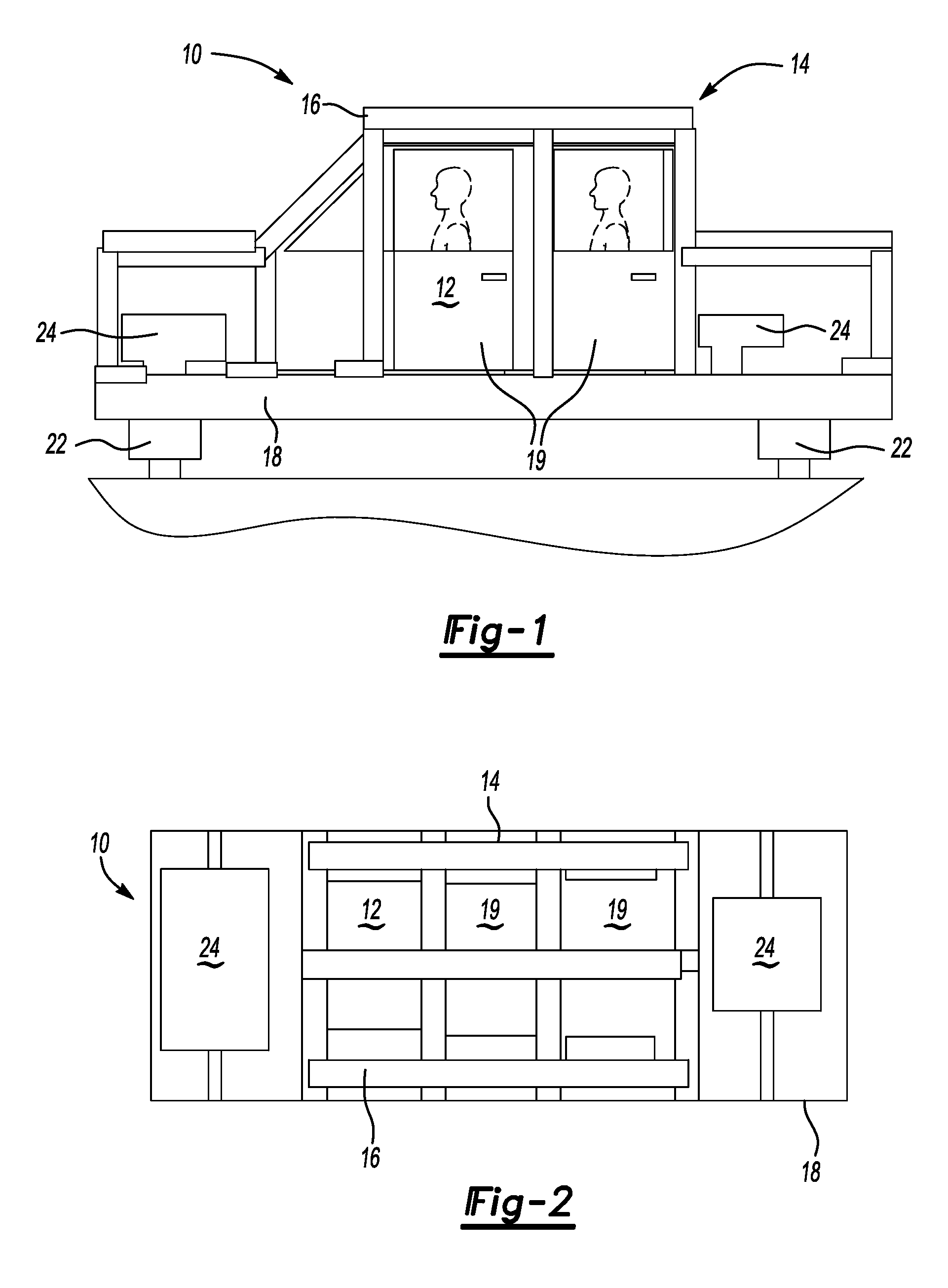
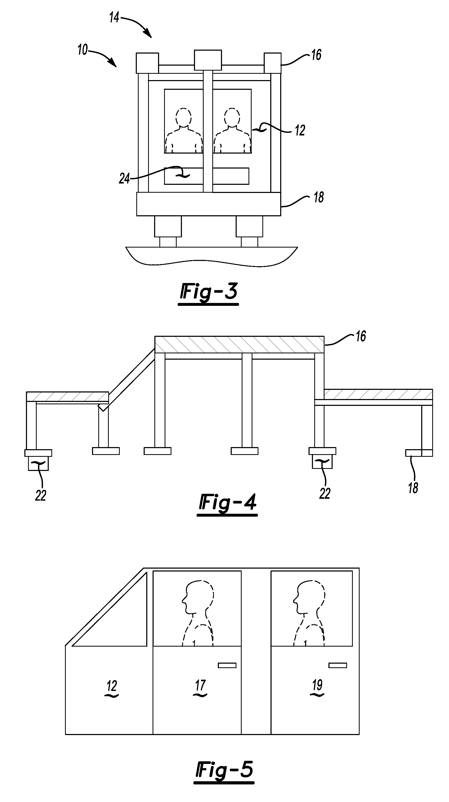
[0028] Referring to FIGS. 1-6a, a portion of a test apparatus 10 according to the invention is shown in various views. To maintain consistency throughout this description, the term leading edge shall refer to the side of the test apparatus which will initially experience a tripping impulse. The term trailing edge shall refer to the side of the test apparatus 180 degrees opposite the leading edge. The portion of the test apparatus 10 comprises an occupant compartment 12 and a rigid shell 14. The rigid shell 14 comprises a top portion 16 and a bottom or platform portion 18. The occupant compartment 12 is rigidly attached to the platform portion 18 by means of welding or conventional fasteners such as bolts. The occupant compartment 12 represents a portion of the simulated vehicle. The platform portion 18 supports the occupant compartment 12.

[0029] The occupant compartment 12 can be constructed from a specific vehicle by removing the suspension, power train and fuel system components....


PUM

PropertyMeasurementUnit
angular velocityaaaaaaaaaa
energy absorbingaaaaaaaaaa
velocityaaaaaaaaaa

Abstract

The invention is an apparatus for simulating attributes of a vehicle during a certain inertial event. The apparatus comprises a rigid shell, an occupant compartment surrounded by the rigid shell, and a carriage supporting the occupant compartment and the rigid shell. The test apparatus transforms the vehicle into a system of reusable components. The rigid body shell eliminates damage to body components by protecting the occupant compartment. The invention also provides a method of simulating a tripped rollover event of a vehicle with the test apparatus and a cart.

Description

FIELD OF THE INVENTION [0001] This invention relates to an apparatus and a method for simulating vehicle rollover crash testing and more particularly, to an apparatus and a method which are adapted to provide repeatable, non-destructive and reliable rollover simulations. BACKGROUND OF THE INVENTION [0002] Rollover crash tests are commonly used in the development of rollover detection sensors, algorithms and occupant protection systems. As in many other crash tests, partial damage or complete destruction of the vehicle is not uncommon. The building of new vehicle prototypes alone is a costly endeavor which requires engineers to attempt to maximize the amount of data and analysis gained from a limited number of crash tests available. [0003] Due to the limited availability of destructive crash tests, a majority of the tests used to develop current rollover detection algorithms and occupant protection systems are laboratory based. Safety engineers and researchers have sought to develop ...

Claims


Application Information

Patent Timeline
Patent Type & Authority Applications(United States)
IPC IPC(8): G01N17/00
CPCG01M17/0078
Inventor MCCOY, ROBERT
Owner FORD GLOBAL TECH LLC
Why Eureka
Try Eureka