
Railway vehicle

Inactive Publication Date: 2006-09-21
HITACHI LTD
View PDF9 Cites 32 Cited by
  • Summary
  • Abstract
  • Description
  • Claims
  • Application Information

AI Technical Summary

Benefits of technology

[0008] Therefore, the object of the present invention is to provide a railway vehicle capable of creating a wide interior space. Actually, the present invention aims at expanding the overhead space within the passenger cabin by improving the structures and layouts of the service facilities for passengers disposed on the shoulder portions and ceiling portions of the interior of the passenger cabin of the car body, and aggregating the functions thereof.
[0010] Since the interior assembly is fixed to the roof structure, it is not so much influenced by production errors and assembly errors of the various blocks constituting the car body, and the attaching operation of the interior assembly to the roof structure can be performed easily.

Problems solved by technology

Thus, the overhead space of passengers is restricted by the various equipments installed at the center in the width direction of the ceiling portion of the interior of the passenger cabin.
In some car body structures, there are not even enough space for installing display terminals and banner advertisements.
Therefore, according to production errors of the side structures and roof structures or the assembling errors thereof, the fixing positions of the shoulder inner panels may not correspond correctly with the side structures and the roof structure.
Accordingly, the mounting operation of the shoulder inner panels may take too much time.

Method used


Image

  • Railway vehicle
  • Railway vehicle
  • Railway vehicle

Examples


Embodiment Construction

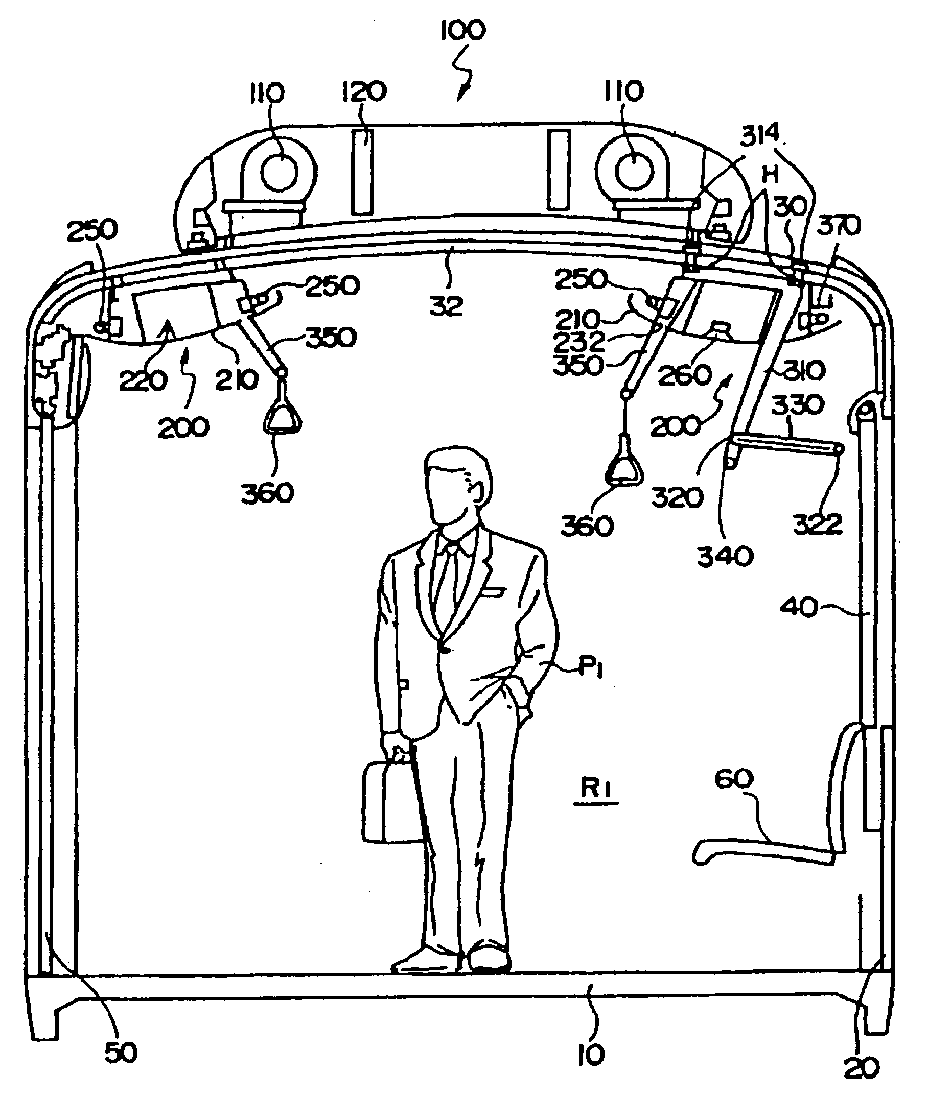
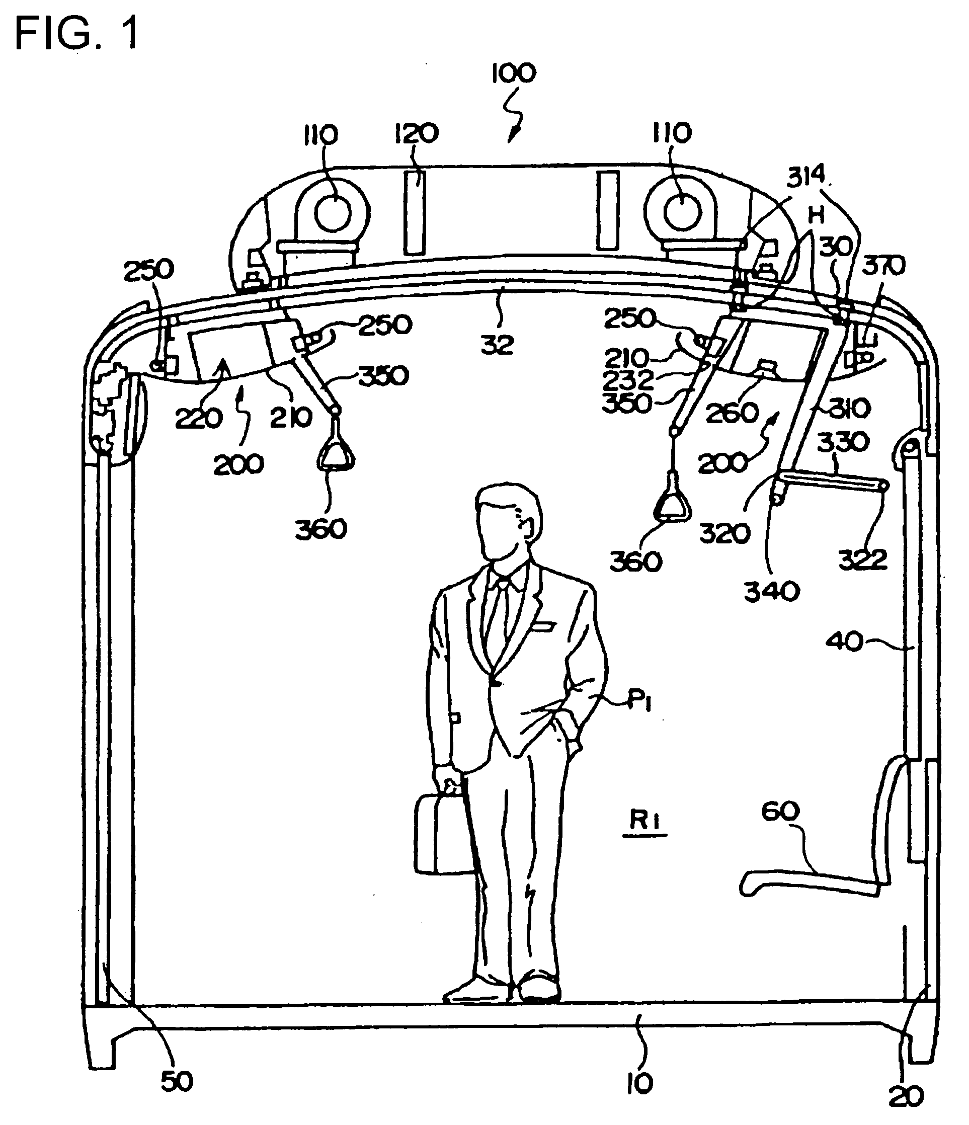
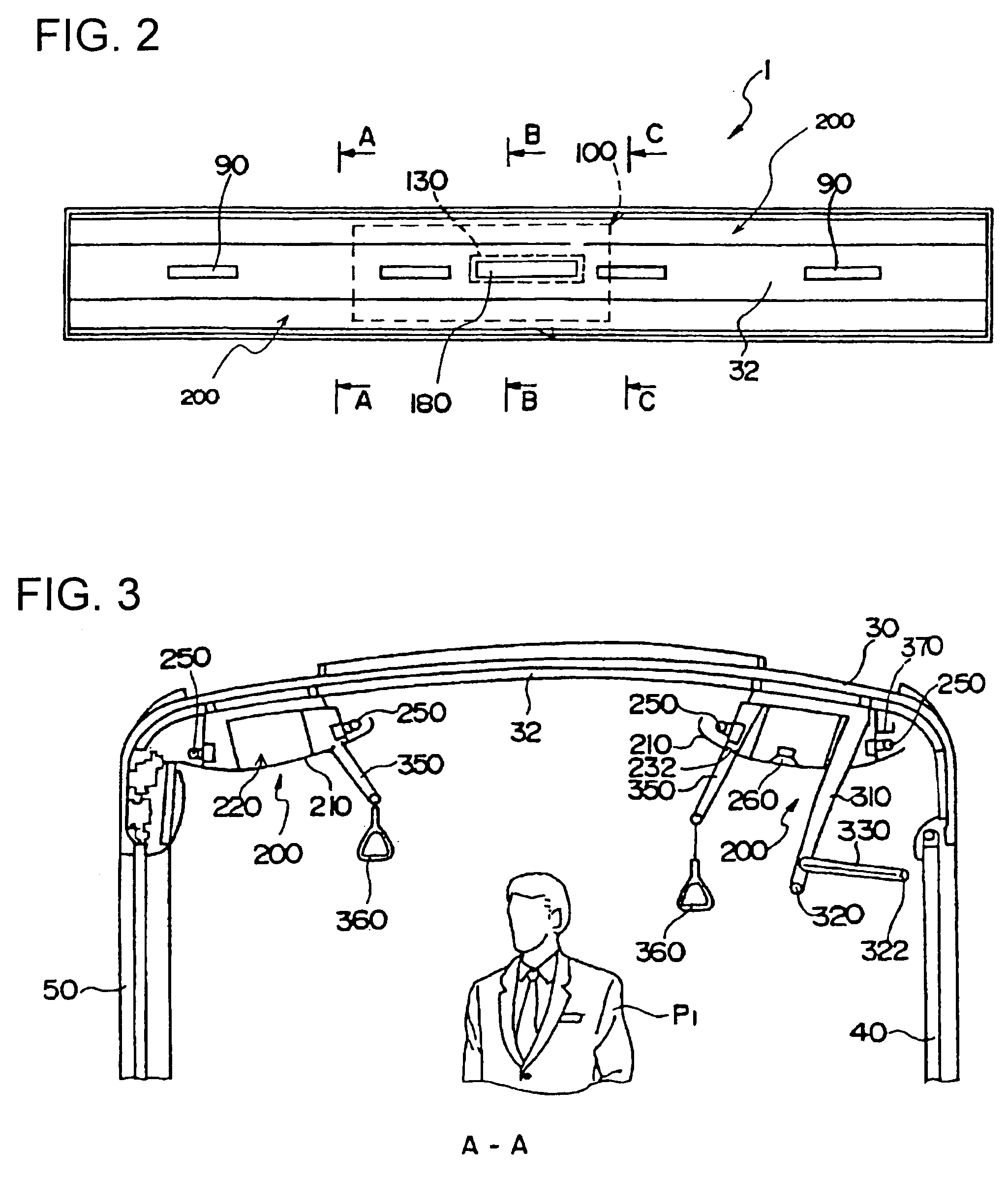
[0025]FIG. 1 is a cross-sectional view showing the general outline of a railway vehicle according to the present invention.

[0026] A car body of the railway vehicle denoted as a whole by reference number 1 is composed of an underframe 10, side structures 20, a roof structure 30 and soon. The side structure 20 includes window glasses 40 and doors 50 for entering and exiting the car body. A passenger cabin R1 is defined by the underframe 10, the side structures 20 and the roof structure 30. Moreover, passenger seats 60 are attached to the inner side of the side structures 20 to serve passenger P1. The longitudinal ends of the car body of the passenger cabin R1 are composed of end structures or passenger cabin partitions, but their reference numbers are omitted in the drawings.

[0027] An air conditioning unit 100 is disposed on the upper portion of the roof structure 30. The side structures 20 and the roof structure 30 are made up of aluminum alloy hollow extruded shape members. The ai...


PUM


Abstract

The invention provides a passenger cabin of a railway vehicle with increased interior space. A multifunction module 200 including an air conditioning duct 220, an illuminating apparatus 250, a speaker 260 and the like is disposed on a connecting portion (shoulder portion) between a roof structure 30 and a side structure 50 of a railway vehicle. A baggage rack bracket 310 and a hand strap bracket 350 are passed through and hung from the roof structure 30. A connecting block connecting the brackets 310 and 350 at the upper portions and being fixed to the air conditioning duct 220 is attached to the roof structure 20. Since the multifunction module 200 is fixed only to the roof structure 30, the attaching operation thereof is facilitated. Since the air conditioning duct 220 is disposed on the shoulder portion, the height of the interior space of the vehicle at the center in the width direction of the car body can be increased. An inside panel 210 for improving the appearance of the multifunction module 200 is further disposed.

Description

[0001] The present application is based on and claims priority of Japanese patent application No. 2006-35715 filed on Feb. 13, 2006, the entire contents of which are hereby incorporated by reference. BACKGROUND OF THE INVENTION [0002] 1. Field of the Invention [0003] The present invention relates to railway vehicles having wider effective space within the passenger cabins so as to provide improved passenger service. The term “railway vehicle” includes railway cars, monorail cars and the like. [0004] 2. Description of the Related Art [0005] In the interior of a passenger cabin of a railway vehicle, in addition to facilities used directly by the passenger such as passenger seats, hand straps and overhead baggage racks, there are provided air conditioning apparatuses such as air conditioning ducts and fans, devices such as lighting apparatuses and speakers, and advertisements. [0006] As disclosed in Japanese Patent Application Laid-Open Publication No. 11-222125 (patent document 1), ac...

Claims


Application Information

Patent Timeline
IPC IPC(8): B61D17/00
CPCB60H1/00371B60H2001/00235B61D17/12B61D27/00A63H1/00A63H1/20A63H33/084A63H33/40G09F19/02
Inventor TODORI, SEIJIROTANII, YASUNORINISHIYAMA, KANJIHIROSE, SHINGO
Owner HITACHI LTD
Learn More