

Fuel tank structure
a fuel tank and structure technology, applied in the direction of rigid containers, transportation and packaging, transportation items, etc., can solve the problems of increasing the volume occupied by standoffs, the deformation mode of the upper and lower surfaces of the fuel tank due to negative pressure, and the effect of suppressing deformation of the fuel tank
- Summary
- Abstract
- Description
- Claims
- Application Information
AI Technical Summary
Benefits of technology
Problems solved by technology
Method used
Image

Examples
first embodiment
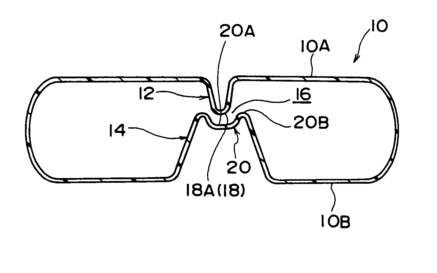
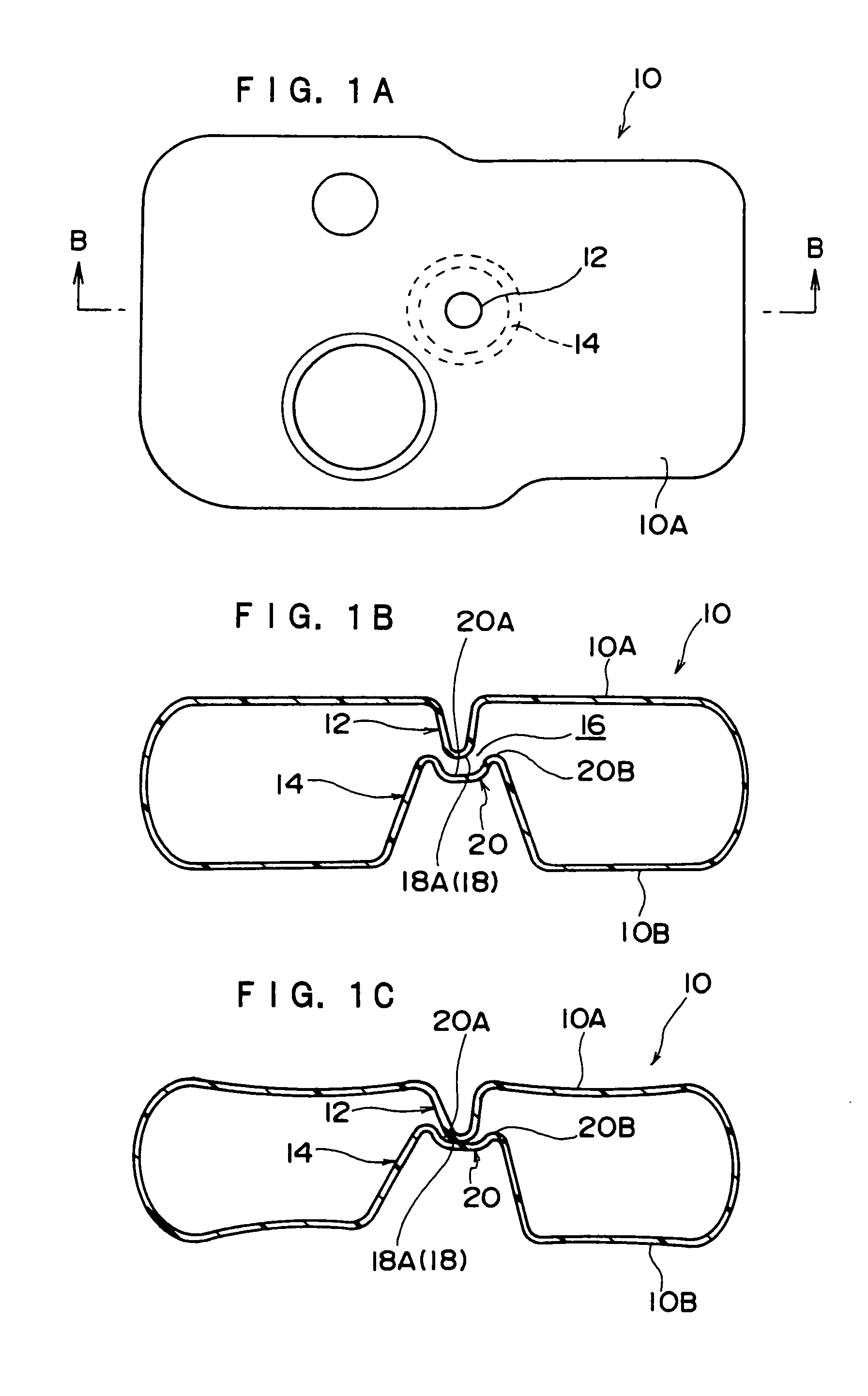
[0018] Referring now to FIGS. 1A-1C, a first embodiment of a fuel tank structure according to the present invention is described below.
[0019]FIG. 1A is a schematic plan view of a fuel tank in the present embodiment, and FIG. 1B is a longitudinal sectional view along line B-B of the fuel tank.
[0020] As shown in FIG. 1A, a fuel tank 10 has a thin and substantial rectangular parallelepiped shape and is formed of resin materials. The fuel tank 10 is fixed to the lower side of the car body floor by using a long tank band or a buckle not shown. The car body floor includes materials (members) mounted on the car body floor.
[0021] As shown in FIG. 1B, nearly at the center of a peak wall 10A as a tank upper surface of the fuel tank 10, an upper stand-off 12 is formed integrally as one interference section projecting inward in the tank (toward a bottom wall 10B) and formed to be nearly conical trapezoid. Similarly, nearly at the center of the bottom wall 10B as a tank lower surface of the f...
second embodiment
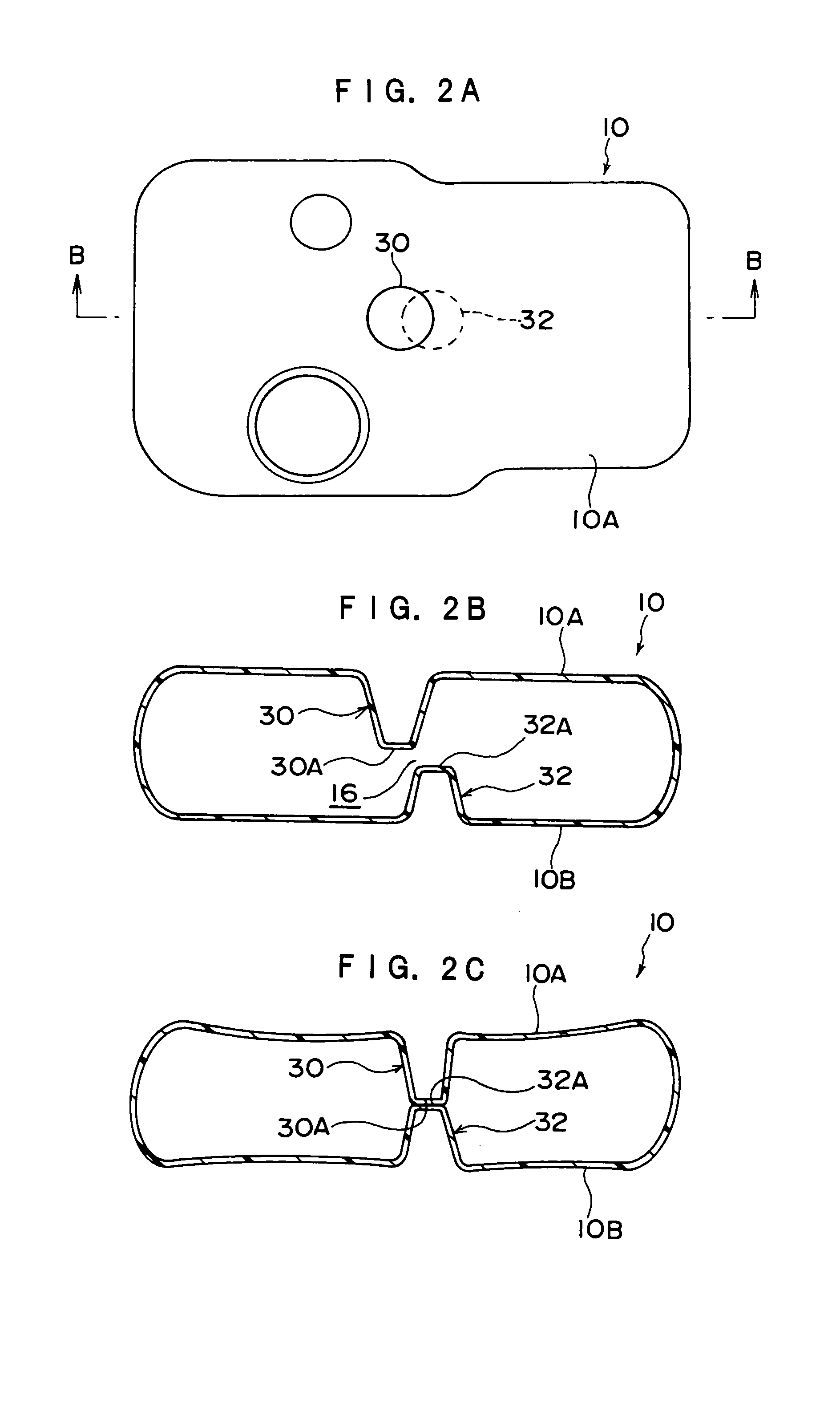
[0032] Referring now to FIGS. 2A-2C, a second embodiment of a fuel tank structure according to the present invention is described below. The same parts as in the first embodiment are identified with the same reference numerals, and explanation thereof is omitted.
[0033] As shown in FIGS. 2A and 2B, the second embodiment is characterized by an upper stand-off 30 and a lower stand-off 32 of similar shape which are formed from the peak wall 10A and the bottom wall 10B of the fuel tank 10, respectively, and the upper stand-off 30 is deviated (offset) from the lower stand-off 32 by a specified distance in plan view.
[0034] According to this structure, when a negative pressure of a specified value or higher is applied in the fuel tank 10, as shown in FIG. 2C, the upper stand-off 30 and the lower stand-off 32 relatively move in the mutually approaching direction, and abutting faces 30A and 32A thereof confront each other. In other words, in this embodiment, direction and extent of deformat...
third embodiment
[0037] Referring now to FIGS. 3A-3C, a third embodiment of a fuel tank structure according to the present invention is described below. The same parts as in the first embodiment are identified with the same reference numerals, and explanation thereof is omitted.
[0038] As shown in FIGS. 3A and 3B, in the third embodiment, an upper stand-off 40 and a lower stand-off 42 of similar shape are formed from the peak wall 10A and the bottom wall 10B of the fuel tank 10, and an abutting face 40A of the upper stand-off 40 and an abutting face 42A of the lower stand-off 42 are formed by the slopes of specified angles not parallel to each other.
[0039] According to this structure, when negative pressure is not applied in the fuel tank 10, as shown in FIG. 3B, the abutting face 40A of the upper stand-off 40 and the abutting face 42A of the lower stand-off 42 are formed in planes not parallel to each other. In this state, as shown in FIG. 3C, when a negative pressure of a specified value or highe...
PUM
 Abstract
Description
Claims
Application Information