Self-sealing male connector

a male connector and self-sealing technology, applied in the field of medical fluid flow connectors, can solve the problems of toxic chemical reagents used, easy to be damaged, and the free end of the syringe and any residual fluids therein are unsealed and exposed,

Inactive Publication Date: 2006-09-21
CAREFUSION 303 INC
View PDF18 Cites 33 Cited by
  • Summary
  • Abstract
  • Description
  • Claims
  • Application Information

AI Technical Summary

Benefits of technology

[0015] In other aspects, the post tip terminates in a substantially rounded nose so as to have a nose apex, and the internal lumen intersects the nose apex with the opening being oriented in a longitudinal direction. In another approach, the internal lumen terminates proximally of the nose apex, and one or more radial cross-holes are formed in the post tip so as to communicate with the internal lumen with openings of the cross holes being oriented in a radial direction. In yet another approach, a cross-notch is formed through the post tip substantially at the nose apex so as to form opposing distally-projecting teeth at the post tip to facilitate opening a slit in the distal end of the boot and the passage of the post tip therethrough.
[0016] Further aspects include the boot being longitudinally compressible and formed at the distal end with a closure wall over the distal fluid opening, the boot having a boot opening therein for being opened by the distal tip upon compression of the boot. The body has a first groove into which is mounted the thread hub. The body has a second groove into which is mounted the boot. The thread hub is rotatably mounted to the first groove so it can rotate independently of the body whereby the body and female connector may remain rotationally stationary while being engaged together while the thread hub is rotated to fasten the female and male together. The hub is formed at a proximal end with a radially inwardly projecting annular hub flange defining an annular first hub opening, the hub flange being configured for receipt within the first groove so as to rotationally mount the hub onto the body while axially trapping the hub flange within the first groove so as to limit the hub's longitudinal movement. The first and second grooves are formed on a proximal base of the post.
[0017] Additional aspects include the post comprising a mounting groove and the boot comprises a resilient mounting lip for receipt in the mounting groove to thereby hold the boot in position on the post. The post has a proximal base and is then tapered to the distal tip wherein the proximal base has a larger diameter than the distal tip whereby the taper facilitates the boot returning to a covering relationship with the body.
[0019] Other aspects include a self-sealing male connector for connecting to a female connector having a generally tubular barrel with external thread portions, the self-sealing male connector comprising a body having a proximal end and a distal end, the proximal end having a fluid flow opening and the distal end being configured as an elongate post extending distally of a shoulder and having a proximal post portion that is cylindrical in form and a distal post portion that is tapered to a smaller-diameter distal post tip, the proximal post portion being formed with adjacent first and second grooves, and wherein an internal lumen communicates between the proximal and distal ends, a resilient boot mounted in covering relationship about the post in the second groove, the boot being configured along a distal end with a generally diametrical slit and being further configured so as to cover the distal end of the post when the boot is in an at-rest condition, thereby restricting fluid within the internal lumen from escaping, and a male thread hub having internal threads and mounted circumferentially about the boot and the post in the first groove such that there exists nothing between the hub and boot at the distal end, whereby engagement of the hub with the female connector along the hub's internal threads and the female connector's thread portions serves to bring the distal end of the boot into contact with the female connector to thereby compress the boot, causing the post tip to protrude through the slit, and allowing fluid communication between the self-sealing male connector and the female connector through the internal lumen.

Problems solved by technology

However, the free end of the syringe and any residual fluids remaining therein are unsealed and exposed.
In the case of chemotherapy, some of the chemical reagents that are used are toxic and the care giver should avoid contact with them.
It is more difficult to do so when the male connector is not sealed.
Both situations are highly undesirable.
Yet, with the existing connectors known and used in the art, the isotope may be sealed off while still in its vial prior to administration, and may be sealed off on the patient side of the typical self-sealing female needle-free connector after administration, as discussed above, but the syringe or other device used to transfer the isotope from its container to the patient during administration is unsealed and could allow undesired exposure to the isotope.
Some sealed male needle-free connectors have been known in the art; however, in some cases, numerous parts with relatively small tolerances make such connectors difficult to manufacture at a lower cost.

Method used


Image

  • Self-sealing male connector
  • Self-sealing male connector
  • Self-sealing male connector

Examples


Embodiment Construction

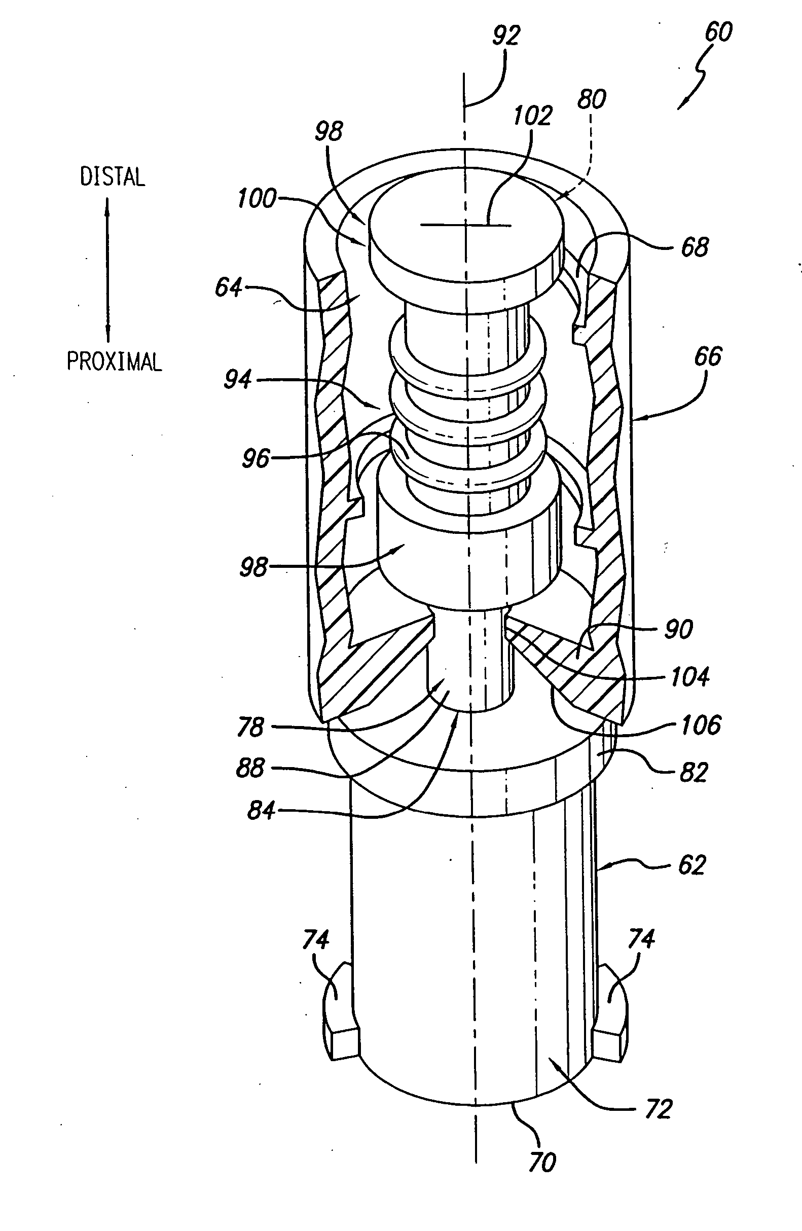
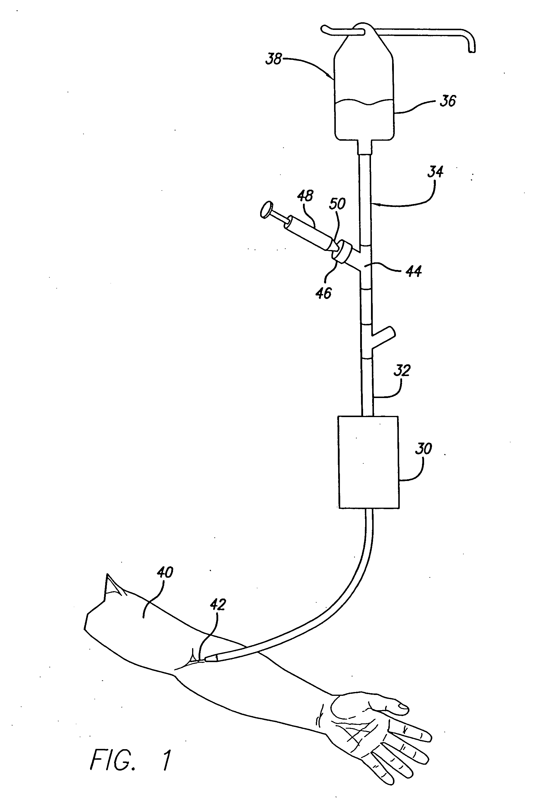
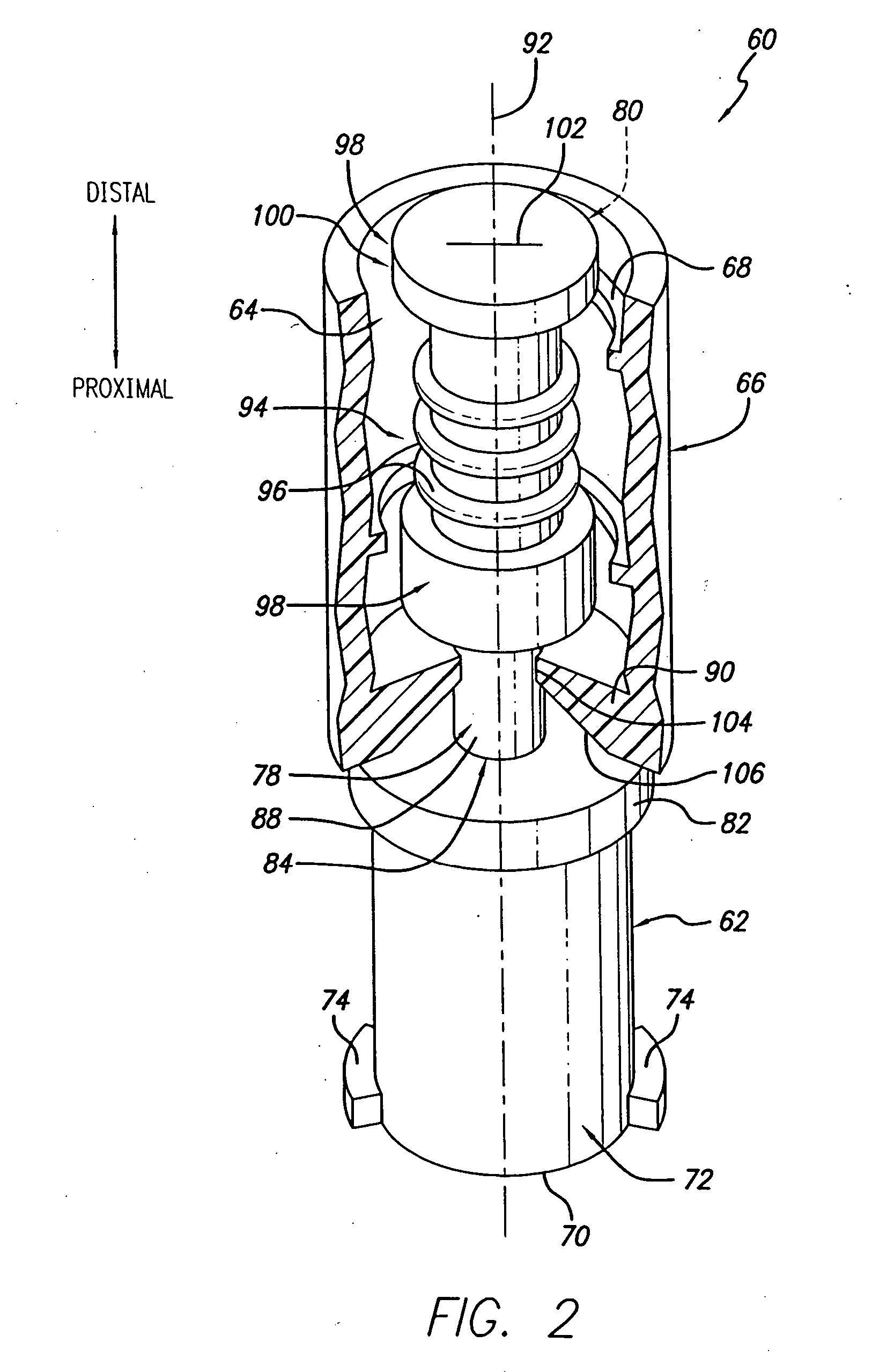
[0053] As shown in the drawings for purposes of illustration, wherein like reference numerals designate corresponding or like elements among the several views, there is shown in FIG. 1 a typical infusion arrangement. An infusion pump 30 is operating on the tubing 32 of an administration set 34 to precisely control the infusion of a medical fluid 36 from a fluid source 38, in this case a suspended bag, to a patient 40. The tubing terminates at its distal end in a cannula 42 that has been introduced to a blood vessel of the patient through which the medical fluid is infused into the patient. Mounted to the tubing is a Y-connector 44 having a female port or connector 46 comprising an integral and internal valve. This connector 46 may take the form of that shown in U.S. Pat. No. 5,676,346, referenced above. A syringe 48 having a further medical fluid has been connected with the female connector. In this case, the syringe has a male tip 50 that has been introduced to the female connector...


PUM


Abstract

A self-sealing male connector having a body, a resilient boot mounted over the body, and a male thread hub. The body is formed with an elongate post that extends to the distal end. The body includes a fluid flow lumen extending from its proximal end to its distal end. At its proximal end, the body may be formed as a female Luer connector, or may be directly connected to tubing, or other arrangements. The internal fluid flow lumen extends through the post to its distal end. The body includes a first groove in which is mounted the boot. In a second groove is mounted the thread cuff. The thread cuff is used to engage a female connector and through thread action, draw in into engagement with the post. As the female connector is further engaged with eh sealed male connector, the post protrudes through the boot and into fluid communication with the female fluid flow passage thus establishing a flow path through both connectors. The boot forms a seal with the female connector when engaged and returns to seal the male connector post and fluid flow passage within disconnected from the female connector.

Description

BACKGROUND [0001] The invention relates generally to medical fluid flow connectors having valves, and more particularly to self-sealing, needle-free, male connectors. [0002] Male and female medical fluid connectors are used in a variety of medical applications. One common application is where there is a desire to interconnect a medical device with tubing material that forms a part of a patient's intravenous (“IV”) medical fluid administration set. Such administration sets typically include one or more female connectors into which may be inserted a male connector to establish fluid communication. The female connectors typically include an internal valve that is activated, or opened, by insertion of the male connector into the female connector. Once the internal valve is open, fluid may flow through both the female and male connectors in either direction. The most common types of IV fluid exchanges use a syringe fitted with a nozzle that is designed to be received into a female connec...

Claims


Application Information

Patent Timeline
Patent Type & Authority Applications(United States)
IPC IPC(8): F16K51/00A61M39/00A61M39/14A61M39/26
CPCA61M39/26A61M2039/0036A61M2039/1077A61M2039/267Y10S604/905
Inventor RAYBUCK, JOHN
Owner CAREFUSION 303 INC
Why Eureka
Try Eureka