Expanding independent load suspension system

a load suspension and independent technology, applied in the direction of suspensions, trailers, vehicle components, etc., can solve the problems of uneven weight distribution, large weight overhang, and heavy load over bridge, so as to reduce the weight of the load, and reduce the impact of weigh

Inactive Publication Date: 2006-09-21
NEAL ROBERT P +1
View PDF2 Cites 8 Cited by
  • Summary
  • Abstract
  • Description
  • Claims
  • Application Information

AI Technical Summary

Benefits of technology

[0012] Another advantage of the invention is to create an expanding vehicle that will distribute the load evenly over the road surface.
[0013] Another advantage of the invention is to create an expanding vehicle that can carry a heavy load that does not have an excessive amount of structural weight.
[0014] Another advantage of the invention is to create an expanding independent load suspension system with the ability to offset the support to compensate for side slope or super elevation in highway curves.
[0015] Another advantage of the invention is to be able to slide axles in or out to clear road obstacles curbs, cars or high wires.
[0016] Another advantage of the invention is to eliminate the attachment of the wheels together as in the conventional dual wheel concept that concentrates the load in a small uneven footprint on the surface.
[0017] Another advantage of the invention is to create a unique walking beam on an axel cluster that has flat surface areas on the sides instead of round.

Problems solved by technology

Very heavy loads exceeding the regulated weight limits often require special permits from state authorities.
Another common problem is the hauling of massive loads over bridges.
Other problems occur with slopes in the surface either to the front or back or to the side, where the weight is not equally distributed to all of the tires evenly.
This uneven distribution of weight may greatly exceed the highway weight limit and the weight limit on individual tires of the vehicle.
An unforeseen problem in existing vehicles is by the manufacturer increasing the rigidity of the suspension system.
When the vehicle leans to the side a great deal of the weight is transmitted to the outside tires, exceeding predetermined load limits.

Method used


Image

  • Expanding independent load suspension system
  • Expanding independent load suspension system
  • Expanding independent load suspension system

Examples


Embodiment Construction

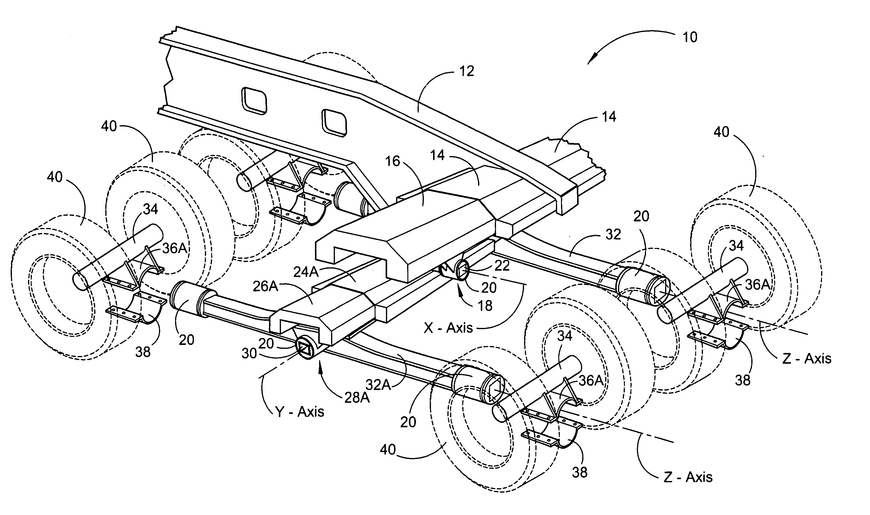
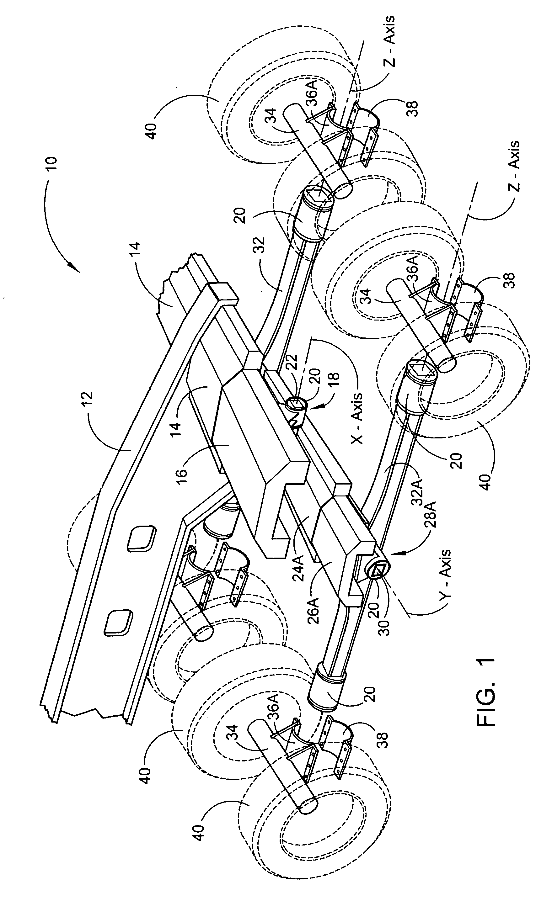
[0073] Referring now to the drawings, wherein similar parts of the expanding independent load suspension system 10 are identified by like reference numerals, there is seen in FIG. 1 a perspective drawing of one side of the expanding independent load suspension system 10 illustrating a conventional frame member 12 fixably attached to the primary box member 14. It must be understood only half of the vehicle has been depicted in the illustration and below this point there will be two or more of each of the items depicted unless otherwise indicated. One of the opposing sliding sections 16 is shown in the extended position. Below the primary sliding sections 16 is one of the primary trunnions 18, housing the bushing 20 and one of the primary square journals 22. The primary square journals 22 will pivot about the X-axis that is parallel to the frame of the vehicle. The primary journals 22 are fixably attached to the top of the secondary box members 24A shown with one of the secondary slid...


PUM


Abstract

An expanding independent load suspension system that incorporates a square walking beam, unique bushings, and multiple expanding sliding units to spread the load bearing tires evenly over the surface instead of grouping them close together. With the weight of the vehicle having the ability to pivot over three separate axes, it maintains an equal pressure on all the tires no matter what the surface conditions. Additional benefits are derived by the separation of the tires with the new design of the square walking beam causing less damage to the roadways. The vehicle has been designed to operate on the highways in the conventional ten-foot width, and then expand to a maximum of twenty feet to move large loads with the permits required.

Description

FIELD OF THE INVENTION [0001] This invention relates to the field of suspension systems to be used on a variety of different load carrying transport vehicles. More specifically, this patent deals with vehicles having multiple axel and tire groupings used to carry heavy loads. The expansion of these vehicles in the past has been limited due to the uneven distribution of the load weight over the wheels, which are normally clustered together. Additionally, some of the wide load carrying vehicles must be disassembled for transport to the location where the load must be transported from, assembled to transport the load, then disassembled again for the return. This patent offers a new and unique suspension system that keeps the tires evenly spaced over the surface both front to back and side to side along with equalizing the weight distributed to each of the tires even on uneven surfaces no matter how wide the vehicle is spread. BACKGROUND OF THE INVENTION [0002] The inventors of this Exp...

Claims


Application Information

Patent Timeline
Patent Type & Authority Applications(United States)
IPC IPC(8): B60G5/00
CPCB60G5/02B60G2204/17B60G2300/0262B60G2300/04B60G2300/36
Inventor NEAL, ROBERT P.PATTERSON, TROY N.
Owner NEAL ROBERT P
Why Eureka
Try Eureka