Scanner system and method for detecting corrected portion in scanned object

a scanning system and scanned object technology, applied in the field of extracting text, can solve the problems of bottleneck in developing electronic documentation, inability to ensure the reliability of electric documents, and inability to determine whether documents have been corrected with correction fluid

Inactive Publication Date: 2006-09-21
KK TOSHIBA +1
View PDF4 Cites 18 Cited by
  • Summary
  • Abstract
  • Description
  • Claims
  • Application Information

AI Technical Summary

Benefits of technology

[0012] According to the system and method of the present invention, a portion corrected with correction fluid or the like can be detected in a scanned original. As compared to the conventional scanne...

Problems solved by technology

Accordingly, in the event that a paper document including at least one portion corrected with correction fluid, which is not permitted to be corrected with correction fluid is converted into an electronic document and then the electronic document is stored, the reliability of the electric document cannot b...

Method used


Image

  • Scanner system and method for detecting corrected portion in scanned object
  • Scanner system and method for detecting corrected portion in scanned object
  • Scanner system and method for detecting corrected portion in scanned object

Examples


Embodiment Construction

[0015] A scanner system and a method for detecting a corrected portion in a scanned object according to the present invention will now be described with reference to the accompanying drawings.

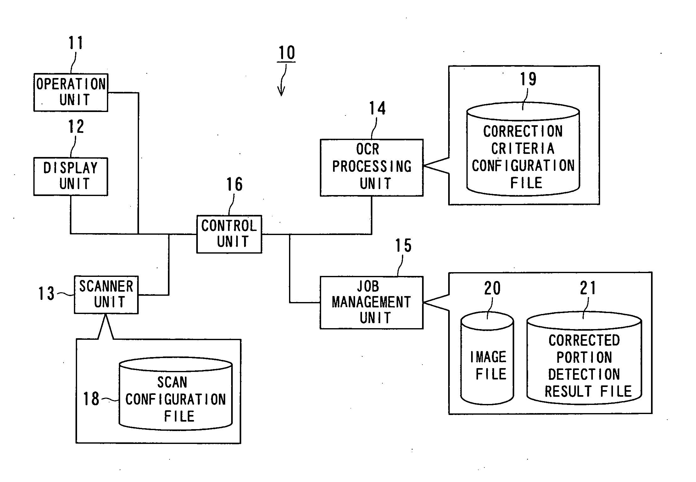
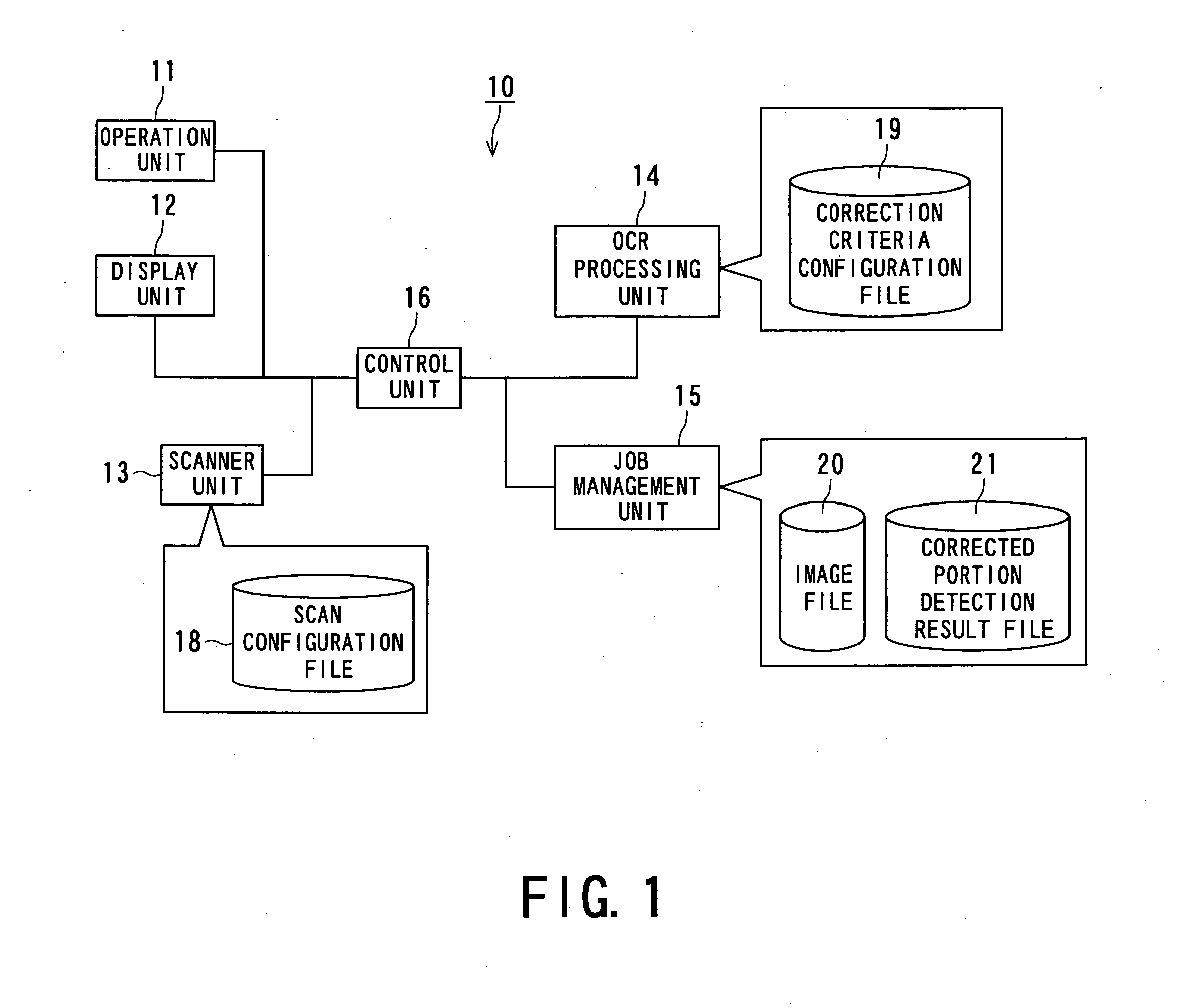
[0016]FIG. 1 is a schematic block diagram of the basic fundamental structure of a scanner system 10 according to an embodiment of the present invention.

[0017] Referring to FIG. 1, the scanner system 10 includes: an operation unit 11 for accepting user input operations, such as a detection mode setting operation and a scan start requesting operation; a display unit 12 for displaying an indication, such as an error indication or an indication about the result of detection, to show information to a user in a visual form; a read unit 13 for converting information written on an original (the surface of a sheet) into image information; a corrected portion detection unit 14 for detecting on the basis of the image information whether each page of the read original includes a corrected portion (correc...


PUM


Abstract

The present invention provides a scanner system and a method for detecting a corrected portion in a scanned object, the system and method being capable of detecting a portion corrected with correction fluid in a scanned original. The scanner system includes: an operation unit for accepting user input operations, such as a detection mode setting operation and a scan start requesting operation; a display unit for displaying an indication, such as an error indication or the result of detection, to show information to a user in a visual form; a read unit for converting information written on a paper original into image information; a corrected portion detection unit for detecting a corrected portion (corrected region) on the basis of the image information; a job management unit for managing the obtained image information and the result of detection; and a control unit for controlling the respective units.

Description

BACKGROUND OF THE INVENTION [0001] 1. Field of the Invention [0002] The present invention relates to a technique of extracting text as image information and, more particularly, to a scanner system and a method for detecting a corrected portion in a scanned object, the system and method being capable of detecting a portion corrected with correction fluid in text upon scanning the text. [0003] 2. Description of the Related Art [0004] Japanese Unexamined Patent Application Publication No. 7-287738 discloses a scanner system and a method for detecting a corrected portion in a scanned object. According to the system and method, a scanner scans an original paper document and a corrected paper document to obtain images (electronic data) and the images are stored as electronic documents. The two electronic documents are compared to each other to obtain the difference therebetween. The difference between the original and corrected documents is displayed. [0005] According to the above-mention...

Claims


Application Information

Patent Timeline
IPC IPC(8): H04N1/04
CPCH04N1/00002H04N1/00037H04N1/00047H04N1/0005H04N1/00076H04N1/00092H04N1/00795H04N1/00801H04N1/00824
Inventor SUENAGA, YOSHIKOMIYACHI, HIROKIMASE, KOUICHI
Owner KK TOSHIBA
Why Eureka
Try Eureka