Digital magnetoresistance sensor

a digital magnetoresistance and sensor technology, applied in the field of magnetoresistance (mr) sensors, to achieve the effect of high magnetoresistance ratio

Inactive Publication Date: 2006-09-21
SAMSUNG ELECTRONICS CO LTD
View PDF1 Cites 2 Cited by
  • Summary
  • Abstract
  • Description
  • Claims
  • Application Information

AI Technical Summary

Benefits of technology

[0007] Illustrative, non-limiting embodiments of the present invention overcome the above disadvantages and other disadvantages not described above. Also, the present invention is not required to overcome the disadvantages described above, and an illustrative, non-limiting embodiment of the present invention may not overcome any of the problems described above. An embodiment of the present invention provides a magnetic sensor with a high magnetoresistance ratio and a discontinuous change in resistance of approximately thousands of percent depending on the existence of an external magnetic field or on magnetic orientation.

Problems solved by technology

In order to realize high recording density, one of the critical issues is how to effectively detect the small magnetic field emanating from the small bits recorded on the medium.

Method used


Image

  • Digital magnetoresistance sensor
  • Digital magnetoresistance sensor
  • Digital magnetoresistance sensor

Examples


first embodiment

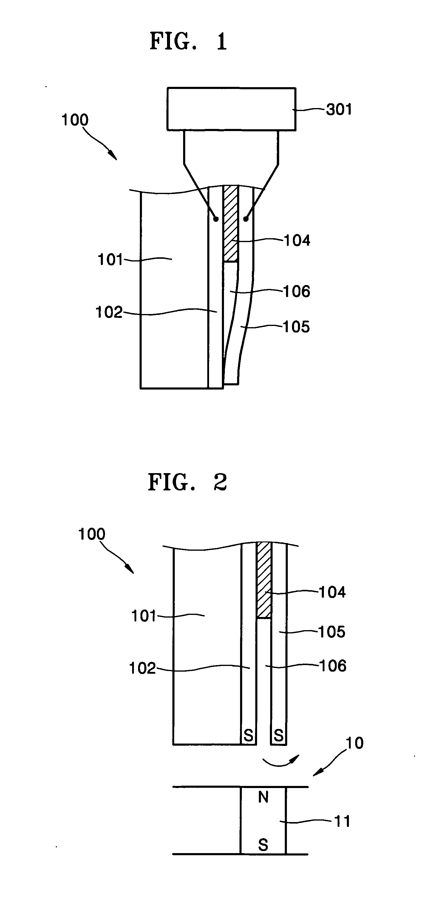
[0019]FIGS. 1 and 2 are schematic views illustrating a MR sensor 100 according to the present invention. The MR sensor 100 includes a substrate 101, a first magnetic layer 102 formed on the substrate 101, an insulating layer 104 partially formed on the first magnetic layer 102, and a second magnetic layer 105, wherein the second magnetic layer 105 has a first portion contacting the upper surface of the insulating layer 104 and a second portion extending beyond the insulating layer 104 and bent towards a part of the first magnetic layer 102. That is, the second portion of the second magnetic layer 105 is structured such that the second portion is movable, and therefore can contact or be spaced apart from the first magnetic layer 102.

[0020] The first and second magnetic layers 102 and 105 are mainly composed of soft magnetic material, and may be in the form of a monolayered or multi-layered thin film. That is, the first and second magnetic layers 102 and 105 can be formed as soft magn...

third embodiment

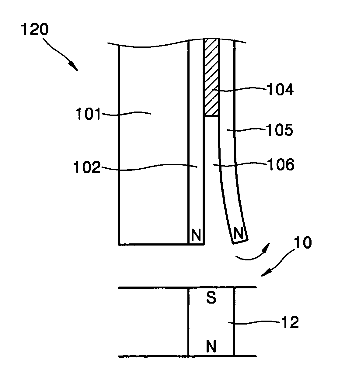
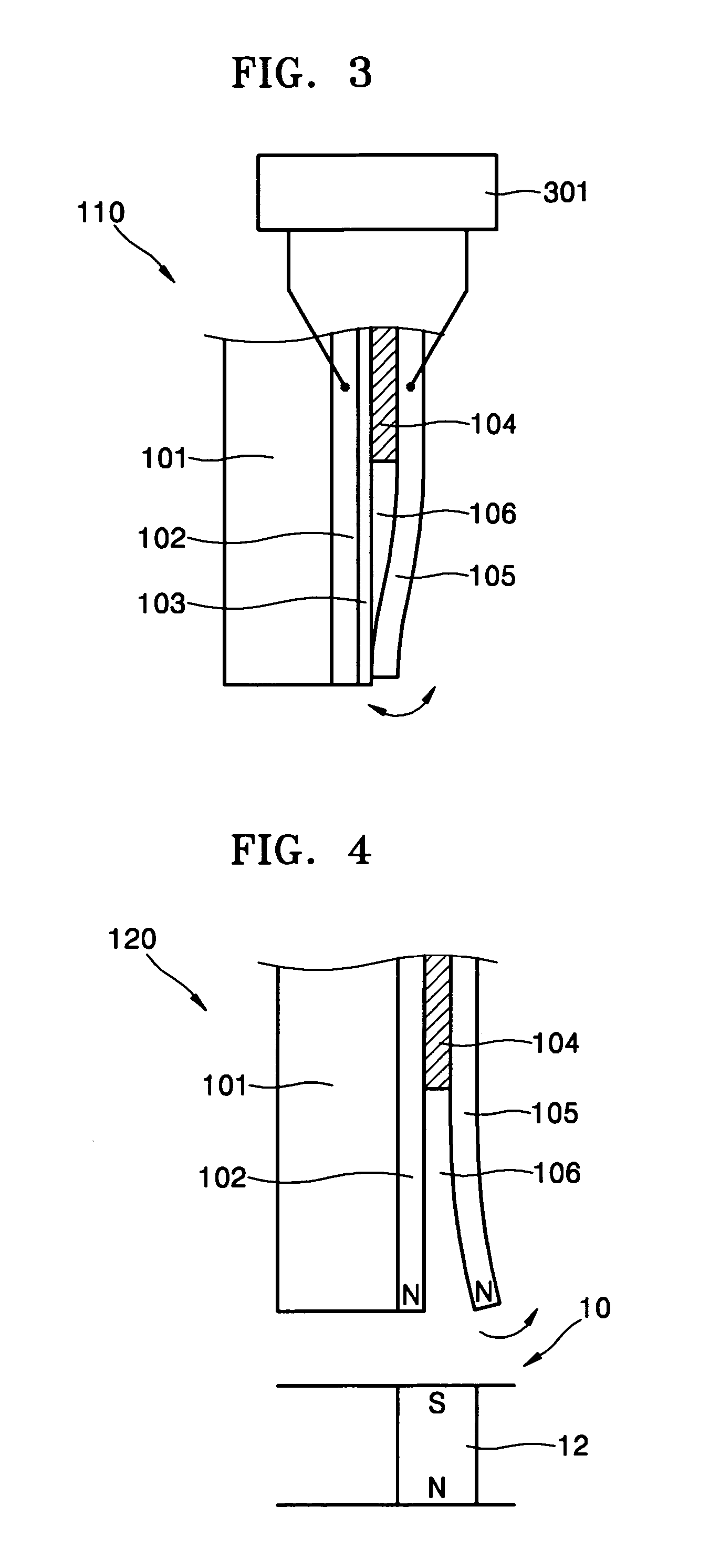
[0029] As illustrated in FIG. 4, when the south pole of a magnetic information area 12 approaches the sensor 120 according to the present invention, the magnetic field of the magnetic information area 12 is applied to the second magnetic layer 105 due to a property of material. So a repulsive force is generated between the first magnetic layer 102 maintaining its magnetization as hard magnetic material and the second magnetic layer 105 so that the second magnetic layer 105 is deformed in a direction away from the first magnetic layer 102. On the contrary, as illustrated in FIG. 5, when the north pole of the magnetic information area 12 approaches the sensor 120, the first magnetic layer 102 maintains its magnetization as the hard magnetic material, and the magnetic field of the magnetic information area 12 is applied to the second magnetic layer 105, exerting an attractive force between the two magnetic layers to mechanically contact each other. In this case, a considerably low resi...

fourth embodiment

[0030]FIGS. 6 through 8 are schematic views illustrating a MR sensor 200 according to the present invention. The sensor 200 includes a substrate 20 and a pair of carbon nano tube resilient members 50, i.e., first and second carbon nano tube resilient members 51 and 52. Each of the pair of carbon nano tube resilient members 50 has at its free end a magnetic member 80. Herein, preferably, a first magnetic member 81 of the first carbon nano tube resilient member 51 is composed of hard magnetic material, and a second magnetic member 82 of the second carbon nano tube resilient member 52 is composed of soft magnetic material.

[0031] Fixed ends of the first and second carbon nano tube resilient members 51 and 52 are preferably fixed to first and second electrodes 21 and 22 of the substrate 20, and the first and second electrodes 21 and 22 are preferably electrically insulated from each other by an insulator 23. The first and second electrodes 21 and 22 are connected to both ends of the resi...


PUM

PropertyMeasurementUnit
coercive forceaaaaaaaaaa
sizeaaaaaaaaaa
diameteraaaaaaaaaa

Abstract

A digital MR sensor with a high magnetoresistance ratio is provided. The MR sensor includes a first magnetic element; and a second magnetic element at least a part of which is resiliently deformable so as to contact with or be separated from the first magnetic element according to a direction of a magnetic force generated between the first and second magnetic elements while the second magnetic element is magnetized under influence of an external magnetic field.

Description

CROSS-REFERENCE TO RELATED PATENT APPLICATION [0001] This application claims the benefit of U.S. Provisional Patent Application No. 60 / 661,916, filed on Mar. 16, 2005 and Korean Patent Application No. 10-2005-0037046, filed on May 3, 2005, in the Korean Intellectual Property Office, the disclosures of which are incorporated herein in their entirety by reference.BACKGROUND OF THE INVENTION [0002] 1. Field of the Invention [0003] Apparatuses and methods consistent with the present invention relate to a magneto-resistive (MR) sensor, and more particularly, to a MR sensor which detects a magnetic field using a change in electric resistance between two magnetic bodies that is caused by the change in an external magnetic field. [0004] 2. Description of the Related Art [0005] Hard disk drives (HDD) are widely used as information storage devices and use magnetic material as an information recording medium. In a HDD, information is recorded by applying strong magnetic field to a local region...

Claims


Application Information

Patent Timeline
Patent Type & Authority Applications(United States)
IPC IPC(8): G11B5/33G11B5/127
CPCB82Y10/00G11B5/3903C11C5/004C11C5/008
Inventor KIM, SUNG-DONGJIN, SUNG-HOOH, HOON-SANG
Owner SAMSUNG ELECTRONICS CO LTD
Why Eureka
Try Eureka