Magnetoresistive element, magnetic head using magnetoresistive element, and magnetic playback device

a technology of magnetoresistance and magnetic head, which is applied in the direction of magnetic recording, instruments, data recording, etc., can solve the problem that the output of magnetoresistance predicted from theoretical calculations has not been obtained, and achieves a large change amount of magnetoresistance, high magnetoresistance ratio, and low electric resistivity

Inactive Publication Date: 2017-08-03
NAT INST FOR MATERIALS SCI
View PDF0 Cites 8 Cited by
  • Summary
  • Abstract
  • Description
  • Claims
  • Application Information

AI Technical Summary

Benefits of technology

[0060]In the present invention, a relatively heavy element Rh.Sn or a magnetic element Ni is not essential unlike the prior art, but an alloy having a bcc structure, for example, a Cu-based alloy such as CuZn or Cu3Al is used for a spacer layer as a material having a low electric resistivity, suitable for the spacer layer. A larger change amount of magnetoresistance can be thereby obtained than a case of using an Ag spacer layer. The Cu alloy having a bcc group structure, used in an example of the present invention, is lattice-matched well with a Heusler alloy regardless of an orientation. Therefore, a high magnetoresistance ratio is obtained regardless of an orientation a Heusler alloy layer.
[0061]Therefore, in an example of the present invention, a CPPGMR element using a Cu alloy having a bcc group structure can be manufactured, and a high magnetoresistive output can be provided. In addition, the CPPGMR element is suitably used for a magnetic head and a magnetic reproducing device using the magnetoresistive element of the present invention.

Problems solved by technology

However, because of magnetic conductivity dependence due to the lattice distortion formed by the Heusler alloy having a bcc group structure and Ag or Cu having a fcc structure and a crystal orientation thereof, such a magnetoresistive output as to be predicted from theoretical calculation has not been obtained.

Method used


Image

  • Magnetoresistive element, magnetic head using magnetoresistive element, and magnetic playback device
  • Magnetoresistive element, magnetic head using magnetoresistive element, and magnetic playback device
  • Magnetoresistive element, magnetic head using magnetoresistive element, and magnetic playback device

Examples


example 1

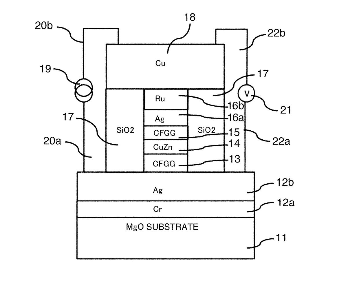
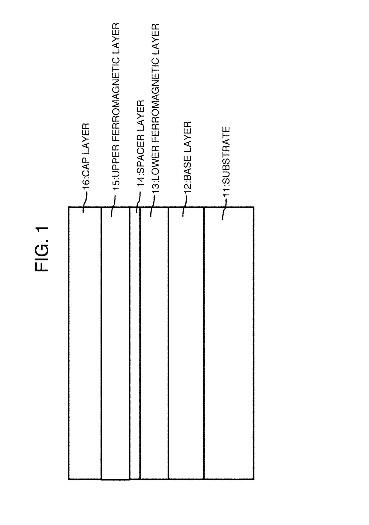
[0077]FIG. 1 is a schematic cross-sectional view of a CPPGMR element according to an embodiment of the present invention. FIG. 4 is a schematic cross-sectional view of an element obtained by adding an electrode for measuring electric resistance with respect to a magnetic field to a CPPGMR element according to an embodiment of the present invention. In FIG. 4, a single crystal MgO substrate is used for the substrate 11, a product obtained by stacking Cr and Ag from the bottom is used for the base layer 12, a Heusler alloy Co2FeGa0.5Ge0.5 (CFGG) is used for each of the lower ferromagnetic layer 13 and the upper ferromagnetic layer 15, CuZn is used for the spacer layer 14, and a product obtained by stacking Ag and Ru from the bottom is used for the cap layer 16.

[0078]In the element illustrated in FIG. 1, a film was formed on an MgO substrate by a sputtering method so as to have a film configuration from the bottom of Cr(10) / Ag(100) / CFGG(10) / CuZn(5) / CFGG(10) / Ag(5) / Ru(8) in which each of...

example 2

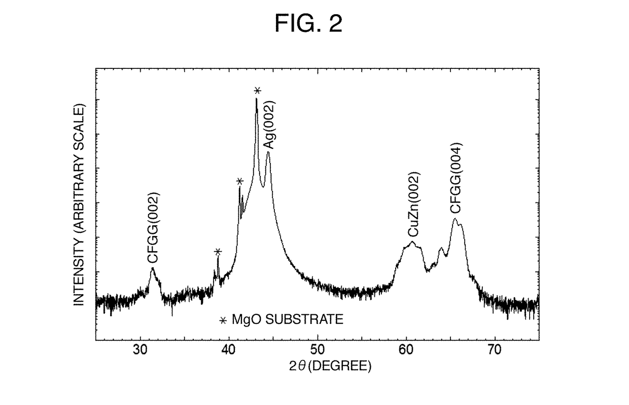
[0084]In Example 2, a stacked structure similar to that in Example 1 is used, but Cu3Al is used as the spacer layer 14 in place of CuZn. That is, a film was formed on an MgO substrate from the bottom by a sputtering method so as to have a film configuration of Cr(10) / Ag(100) / CFGG(10) / Cu3Al(5) / CFGG(10) / Ag(5) / Ru(8). Subsequently, a crystal structure was examined by X-ray diffraction. FIG. 7 is an X-ray diffraction pattern diagram of a CPPGMR element film having the stacked configuration in Example 2. When the pattern diagram is represented by 2θ in the X-ray diffraction, three sharp peaks around 39°, 41°, and 43° due to reflection on the MgO substrate are observed. A peak at 31° should be found due to reflection in a CFGG(002) direction, but is not found because of being buried in a noise. An obtuse peak around 64° is found due to reflection in a CFGG(004) direction. A peak at 43° is found due to reflection in an Ag(002) direction, an obtuse peak around 60° is found due to reflection ...


PUM

PropertyMeasurementUnit
thicknessaaaaaaaaaa
magnetoresistiveaaaaaaaaaa
compositionaaaaaaaaaa

Abstract

The present invention addresses the problem of providing an element which uses the current-perpendicular-to-plane giant magnetoresistance (CPPGMR) effect of a thin film having the three-layer structure of ferromagnetic metal/non-magnetic metal/ferromagnetic metal. The problem is solved by a magnetoresistive element provided with a lower ferromagnetic layer and an upper ferromagnetic layer which contain a Heusler alloy, and a spacer layer sandwiched between the lower ferromagnetic layer and the upper ferromagnetic layer, the magnetoresistive element being characterized in that the spacer layer contains an alloy having a bcc structure. Furthermore, it is preferable for the alloy to have a disordered bcc structure.

Description

TECHNICAL FIELD[0001]The present invention relates to an element using a current-perpendicular-to-plane giant magnetoresistance (CPPGMR) effect of a thin film having a three-layer structure of ferromagnetic metal / non-magnetic metal / ferromagnetic metal, particularly to a magnetoresistive element using a non-magnetic spacer layer having a body-centered cubic (bcc) structure as the non-magnetic metal layer.BACKGROUND ART[0002]The element using a current-perpendicular-to-plane giant magnetoresistance (CPPGMR) effect is formed of a thin film having a three-layer structure of ferromagnetic metal / non-magnetic metal / ferromagnetic metal, and is expected to be used for a reading head for a magnetic disc. An element using a Heusler alloy having a large spin polarizability as a ferromagnetic metal has been studied. For example, Patent Literatures 1 and 2 have proposed use of Cu which is a metal having a face-centered cubic (fcc) structure for a spacer layer (layer of a non-magnetic metal). In a...

Claims


Application Information

Patent Timeline
Patent Type & Authority Applications(United States)
IPC IPC(8): G11B5/39G11B5/127G11B5/40
CPCG11B5/3906G11B2005/3996G11B5/1278G11B5/40G11B5/39H10N50/85H10N50/10
Inventor FURUBAYASHI, TAKAOTAKAHASHI, YUKIKOHONO, KAZUHIRODU, YE
Owner NAT INST FOR MATERIALS SCI
Why Eureka
Try Eureka