Magnetoresistance effect element and magnetic memory

a technology of magnetic memory and effect element, which is applied in the direction of digital storage, semiconductor devices, instruments, etc., can solve the problems of long read time, unable to withstand the voltage of an insulating layer, etc., and achieves high magnetoresistance ratio, easy control of magnetic anisotropy, and large magnetoresistance ratio

Active Publication Date: 2013-06-06
TOHOKU UNIV
View PDF5 Cites 16 Cited by
  • Summary
  • Abstract
  • Description
  • Claims
  • Application Information

AI Technical Summary

Benefits of technology

[0021]By applying the present invention, a magnetoresistance effect element of a magnetic domain wall motion type MRAM that has a large magnetoresistance ratio and a perpendicular magnetization direction with respect to film plane can be easily made. When the magnetoresistance ratio is desired to be controlled, the annealing temperature may be controlled, and the magnetoresistance effect element can be made in which the perpendicular magnetization direction with respect to film plane is maintained by adjusting the film thickness of the pinned layer and the magnetic recording layer formed with the non-magnetic layer sandwiched therebetween. Further, by applying the present invention, magnetic anisotropy can be easily controlled by controlling the film thickness of the pinned layer and the magnetic recording layer. Further, a high magnetoresistance ratio and low damping constant α can be obtained, so that high-speed read and write operations can be performed.

Problems solved by technology

However, in this system, a large current needs to flow through the magnetoresistance effect element itself at the time of writing.
Thus, in the case of the TMR element with an insulator for the non-magnetic layer, the withstand voltage of an insulating layer becomes an issue.
In the case of a GMR element in which an insulating layer is not used in the non-magnetic layer, there is the problem of long read time because of the small resistance ratio.

Method used


Image

  • Magnetoresistance effect element and magnetic memory
  • Magnetoresistance effect element and magnetic memory
  • Magnetoresistance effect element and magnetic memory

Examples


first embodiment

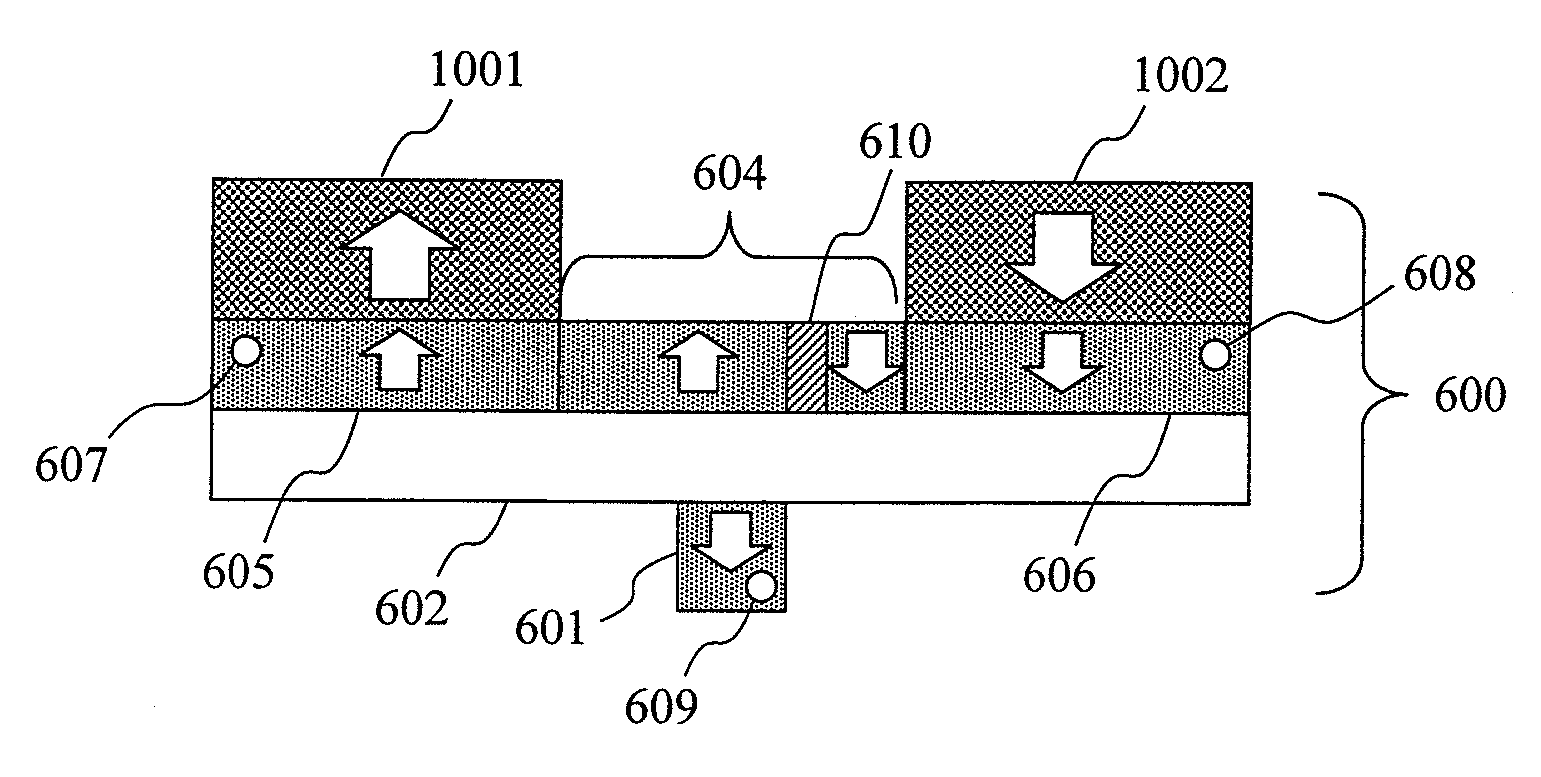
[0042]FIG. 6 schematically shows an example of the magnetoresistance effect element according to the present invention, (a) being a schematic plan view and (b) being a schematic cross sectional view.

[0043]According to an aspect of the present invention, a magnetoresistance effect element 600, as shown in FIG. 6, is provided with a pinned layer 601 which is a ferromagnet with fixed magnetization; a non-magnetic layer 602 stacked on the pinned layer; and a ferromagnetic magnetic recording layer 603 stacked on the non-magnetic layer 602. The non-magnetic layer 602 and the magnetic recording layer 603 have a thin wire shape. The material of the pinned layer 601 and the magnetic recording layer 603 is preferably a ferromagnetic material including at least one type of 3d transition metal element, such as Co or Fe, or a Heusler alloy represented by Co2MnSi and the like. The material of the non-magnetic layer 602 is preferably a material such that the magnetoresistance ratio can be increase...

second embodiment

[0062]According to another aspect of the present invention, the magnetoresistance effect element 600 according to the first embodiment may include a fixed magnetization layer 1801 formed on the interface of the pinned layer 601 on the side opposite to the non-magnetic layer 602 by stacking another conventionally known perpendicular magnetic anisotropy material, such as a multilayer film of Co and Pt, Ni and Pt, and the like, or an FePt or TbFeCo alloy, so as to increase and strongly fix the perpendicular magnetic anisotropy of the pinned layer 610. FIG. 18 shows the magnetoresistance effect element 600 according to this aspect. By adopting this configuration, the perpendicular magnetic anisotropy of the pinned layer 601 can be increased by the ferromagnetic coupling with the perpendicular magnetic anisotropy material. The film thickness is 20 nm when FePt is used for the pinned magnetization layer 1801, for example. For the same purpose, an antiferromagnetic layer may be stacked on ...

third embodiment

[0063]According to another aspect of the present invention, a magnetic domain wall motion type MRAM can be obtained by adopting the magnetoresistance effect element 600 according to the first or the second embodiment as a storage element.

[0064]As shown in FIG. 19, the magnetic domain wall motion type MRAM according to the present invention is provided with two selection transistors for each magnetoresistance effect element 600, and include a plurality of bit lines 1901 disposed in parallel to each other; a plurality of first source lines 1902 disposed in parallel to the bit lines 1901 and parallel to each other; and a plurality of second source lines 1903 disposed in parallel to the bit lines 1901 and the first source lines 1902 and parallel to each other. The magnetic domain wall motion type MRAM also includes first word lines 1904 disposed perpendicularly to the bit lines 1901, the first source lines 1902, and the second source lines 1903 and in parallel to each other; and second ...


PUM


Abstract

Provided are a magnetoresistance effect element with a stable magnetization direction perpendicular to film plane and a controlled magnetoresistance ratio, in which writing can be performed by magnetic domain wall motion, and a magnetic memory including the magnetoresistance effect element. The magnetoresistance ratio is controlled by forming a ferromagnetic layer of the magnetoresistance effect element from a ferromagnetic material including at least one type of 3d transition metal or a Heusler alloy. The magnetization direction is changed from a direction in the film plane to a direction perpendicular to the film plane by controlling the film thickness of the ferromagnetic layer on an atomic layer level.

Description

TECHNICAL FIELD[0001]The present invention relates to a magnetoresistance effect element and a magnetic memory (MRAM: Magnetic Random Access Memory) provided with the magnetoresistance effect element as a memory cell. Particularly, the present invention relates to a MRAM in which a magnetic domain wall motion system is adopted for write operation.BACKGROUND[0002]A MRAM is a nonvolatile memory that is considered a promising candidate for a universal memory from the viewpoint of high integration and high operating speed, for example. In a memory cell of a MRAM, a magnetoresistance effect element, such as a GMR (giant magnetoresistance) element or a TMR (tunnel magnetoresistance) element, is used as a storage element. These elements have a three-layer structure as a basic structure such that a non-magnetic layer is sandwiched between two ferromagnetic layers, i.e., a first ferromagnetic layer and a second ferromagnetic layer. One of the two ferromagnetic layers is a pinned layer with a...

Claims


Application Information

Patent Timeline
Patent Type & Authority Applications(United States)
IPC IPC(8): G11C11/16H01L43/02
CPCG11C11/16H01L27/228G11C11/161H01L43/02G11C11/14H01L43/08G11C11/1675H10B61/22H10N50/10H10N50/80
Inventor OHNO, HIDEOIKEDA, SHOJIMATSUKURA, FUMIHIROENDOH, MASAKIKANAI, SHUNMIURA, KATSUYAYAMAMOTO, HIROYUKI
Owner TOHOKU UNIV
Why Eureka
Try Eureka