Cpp-type magneto resistive effect element having a pair of magnetic layers

a magneto-resistive effect and layer technology, applied in the field of cpp, can solve the problems of large mismatch in lattice constant, difficult to obtain good film characteristics, disturbing crystalline structure, etc., and achieve the effect of high magnetoresistance ratio and soft magnetic characteristics

Inactive Publication Date: 2009-07-09
TDK CORPARATION
View PDF10 Cites 15 Cited by
  • Summary
  • Abstract
  • Description
  • Claims
  • Application Information

AI Technical Summary

Benefits of technology

[0010]It is an object of the present invention to provide a magnetoresistance effect element which is capable of achieving a high magnetoresistance ratio while ensuring soft magnetic characteristics of a magnetic layer whose magnetization direction is variable depending on an external magnetic field (hereinafter also referred to as “variable magnetization direction magnetic layer”). Another object of the present invention is to provide a slider, a hard disk drive, etc. incorporating such a magnetoresistance effect element.

Problems solved by technology

If there is a mismatch in the lattice constant, then the crystalline structure is disturbed at the interface between the adjacent layers, making it difficult to obtain good film characteristics.
If three or more crystalline layers are stacked, then one of the layers may be affected by another crystalline layer that is not directly adjacent to the layer, possibly disturbing the crystalline structure.
Since a crystalline oxide has a particularly large lattice constant, a large mismatch in the lattice constant is caused between the crystalline oxide and another crystalline layer, as compared with the case in which a conventional spacer layer made of a single Cu layer is used.

Method used


Image

  • Cpp-type magneto resistive effect element having a pair of magnetic layers
  • Cpp-type magneto resistive effect element having a pair of magnetic layers
  • Cpp-type magneto resistive effect element having a pair of magnetic layers

Examples


1st embodiment

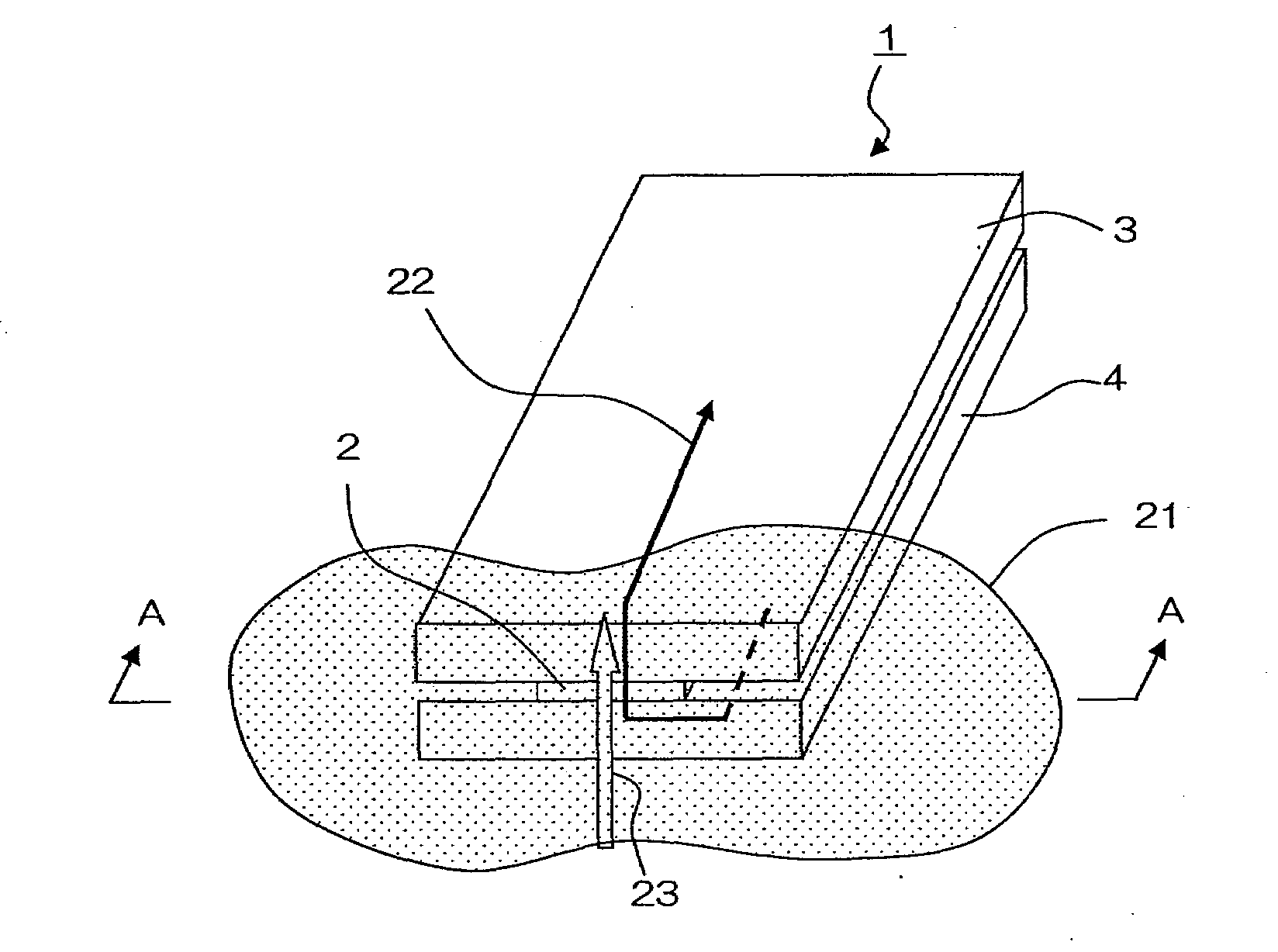
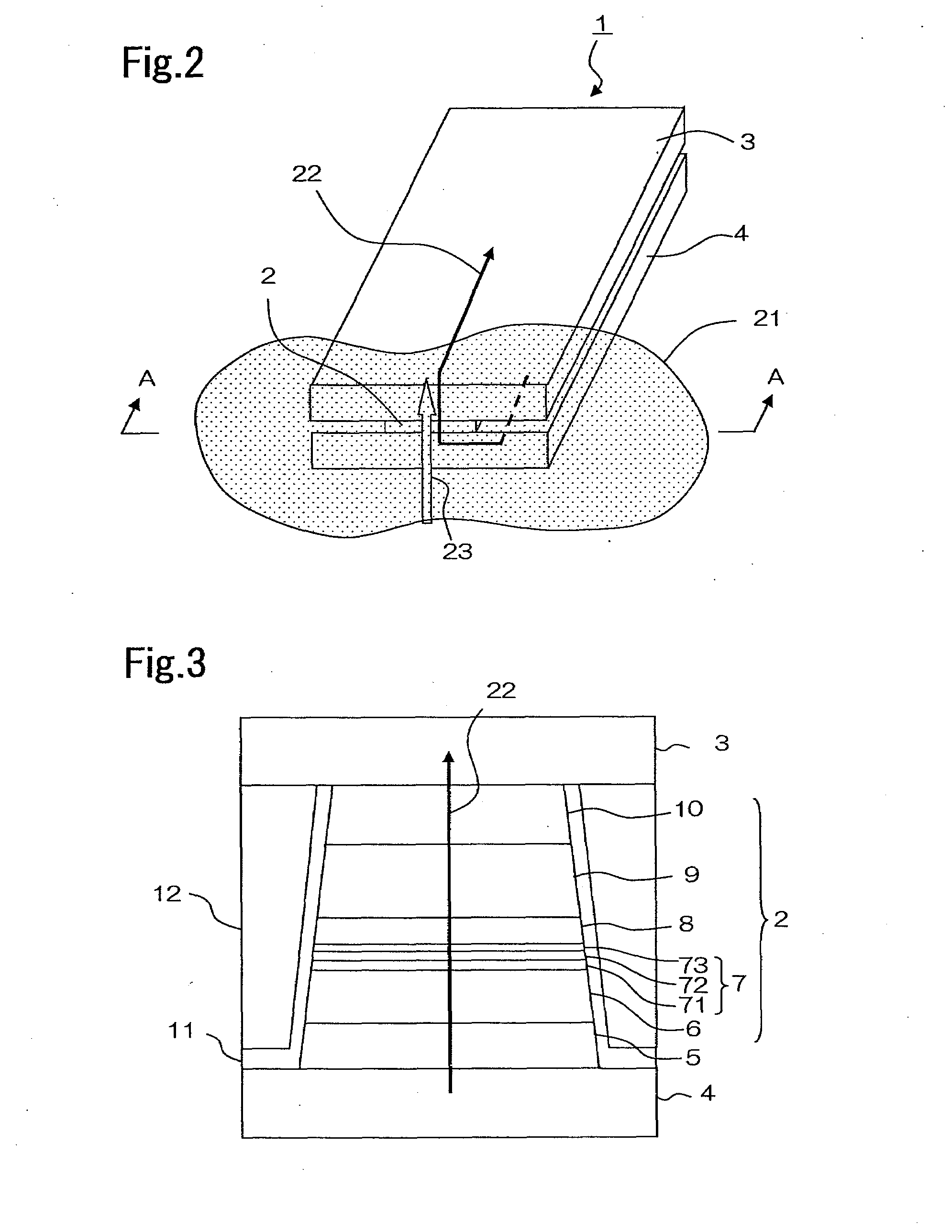
[0039]A magnetoresistance effect element according to the present embodiment is used as a magnetoresistance effect element in a CPP-GMR element. FIG. 2 is a partial perspective view of a thin-film magnetic head that includes magnetoresistance effect element 2 according to the present invention. Thin-film magnetic head 1 may be a read-only head or may be an MR / inductive composite head having a write head portion. Magnetoresistance effect element 2 is arranged between upper electrode shield 3 and lower electrode shield 4 and has a tip end that faces recording medium 21. Magnetoresistance effect element 2 is adapted to allow sense current 23 to flow in a direction that is perpendicular to the film plane under a voltage that is applied between upper electrode shield 3 and lower electrode shield 4. The magnetic field of recording medium 21 at a position that faces magnetoresistance effect element 2 changes in accordance with the movement of recording medium 21 in moving direction 23. Thi...

2nd embodiment

[0054]A second embodiment of the present invention will be described below. A magnetoresistance effect element according to the second embodiment is similar to the first embodiment except that the layer configuration Cu / ZnO / Cu of the spacer layer according to the first embodiment is changed to Cu / ZnO / Zn. Table 2 shows an example of the layer configuration of the stack according to the present embodiment. Similarly to the first embodiment, the present embodiment is used as a magnetoresistance effect element in a CPP-GMR element.

TABLE 2Layer ConfigurationCompositionThickness(nm)Cap Layer 10Ru10Free Layer 9NiFe5CoFeB0.5CoFe1Spacer Layer 8Zn0.7ZnO1.6Cu0.7Pinned Layer 7Inner Pinned Layer 73CoFe3Intermediate Layer 72Ru0.8Outer Pinned Layer 71CoFe3Antiferromagnetic Layer 6IrMn5Buffer Layer 5Ru2Ta1

[0055]FIGS. 5A through 5C show the comparison of coercivity, the magnetostriction and the magnetoresistance ratio between a layer configuration of Cu / ZnO / Cu and a layer configuration of Cu / ZnO / Zn....

3rd embodiment

[0058]A third embodiment of the present invention will be described below. A magnetoresistance effect element according to the third embodiment is similar to the first embodiment except that the layer configuration Cu / ZnO / Cu of the spacer layer according to the first embodiment is changed to MgO. Table 3 shows an example of the layer configuration of the stack according to the present embodiment. The present embodiment is used as a magnetoresistance effect element in a TMR element.

TABLE 3Layer ConfigurationCompositionThickness(nm)Cap Layer 10Ru10Free Layer 9NiFe4CoFeB0.4CoFe0.6Spacer Layer 8MgO1Pinned Layer 7Inner Pinned Layer 73CoFe1CoFeB1.8Intermediate Layer 72Ru0.8Outer Pinned Layer 71CoFe3Antiferromagnetic Layer 6IrMn7Buffer Layer 5Ru2Ta1

[0059]MgO has a crystalline structure, similarly to Cu / ZnO / Cu, and is more apt to affect the soft magnetic characteristics of the free layer than AlOx that has an amorphous structure that has been conventionally used. However, for the same reaso...


PUM

PropertyMeasurementUnit
thicknessaaaaaaaaaa
thicknessaaaaaaaaaa
coercivityaaaaaaaaaa

Abstract

A magnetoresistance effect element comprises: a pair of magnetic layers whose magnetization directions form a relative angle therebetween that is variable depending on an external magnetic field; and a crystalline spacer layer sandwiched between the pair of magnetic layers; wherein sense current may flow in a direction that is perpendicular to a film plane of the pair of magnetic layers and the spacer layer. The spacer layer includes a crystalline oxide, and either or both magnetic layers whose magnetization direction is variable depending on the external magnetic field has a layer configuration in which a CoFeB layer is sandwiched between a CoFe layer and a NiFe layer and is positioned between the spacer layer and the NiFe layer.

Description

BACKGROUND OF THE INVENTION[0001]1. Field of the Invention[0002]The present invention relates to a CPP (Current-Perpendicular-to-the-Plane) type magnetoresistive effect element in which sense current flows perpendicularly to the film plane, and more particularly, to the structure of a spacer layer and magnetic layers of such a magnetoresistive effect element.[0003]2. Description of the Related Art[0004]CIP-GMR (Current In Plane-Giant Magneto-Resistance) elements in which sense current flows parallel to the element film plane have mainly been used as reproducing elements of thin-film magnetic heads. Recently, efforts have been made to develop elements in which sense current flows perpendicularly to the element film plane in order to cope with higher-density magnetic recording. The elements of this type include a TMR (Tunnel Magneto-Resistance) element utilizing the TMR effect and a CPP-GMR element utilizing the GMR effect.[0005]The TMR element and the CPP-GMR element includes a stack...

Claims


Application Information

Patent Timeline
Patent Type & Authority Applications(United States)
IPC IPC(8): G11B5/39G11B5/127
CPCB82Y10/00B82Y25/00H01L43/10G11B5/3929G11B2005/3996G11B5/3909H10N50/10H10N50/85
Inventor TSUCHIYA, YOSHIHIROHARA, SHINJIMIZUNO, TOMOHITOMIURA, SATOSHIYANAGISAWA, TAKUMI
Owner TDK CORPARATION
Why Eureka
Try Eureka