
Magnetic read head and magnetic read write system

Inactive Publication Date: 2008-07-24
HITACHI LTD
View PDF14 Cites 10 Cited by
  • Summary
  • Abstract
  • Description
  • Claims
  • Application Information

AI Technical Summary

Benefits of technology

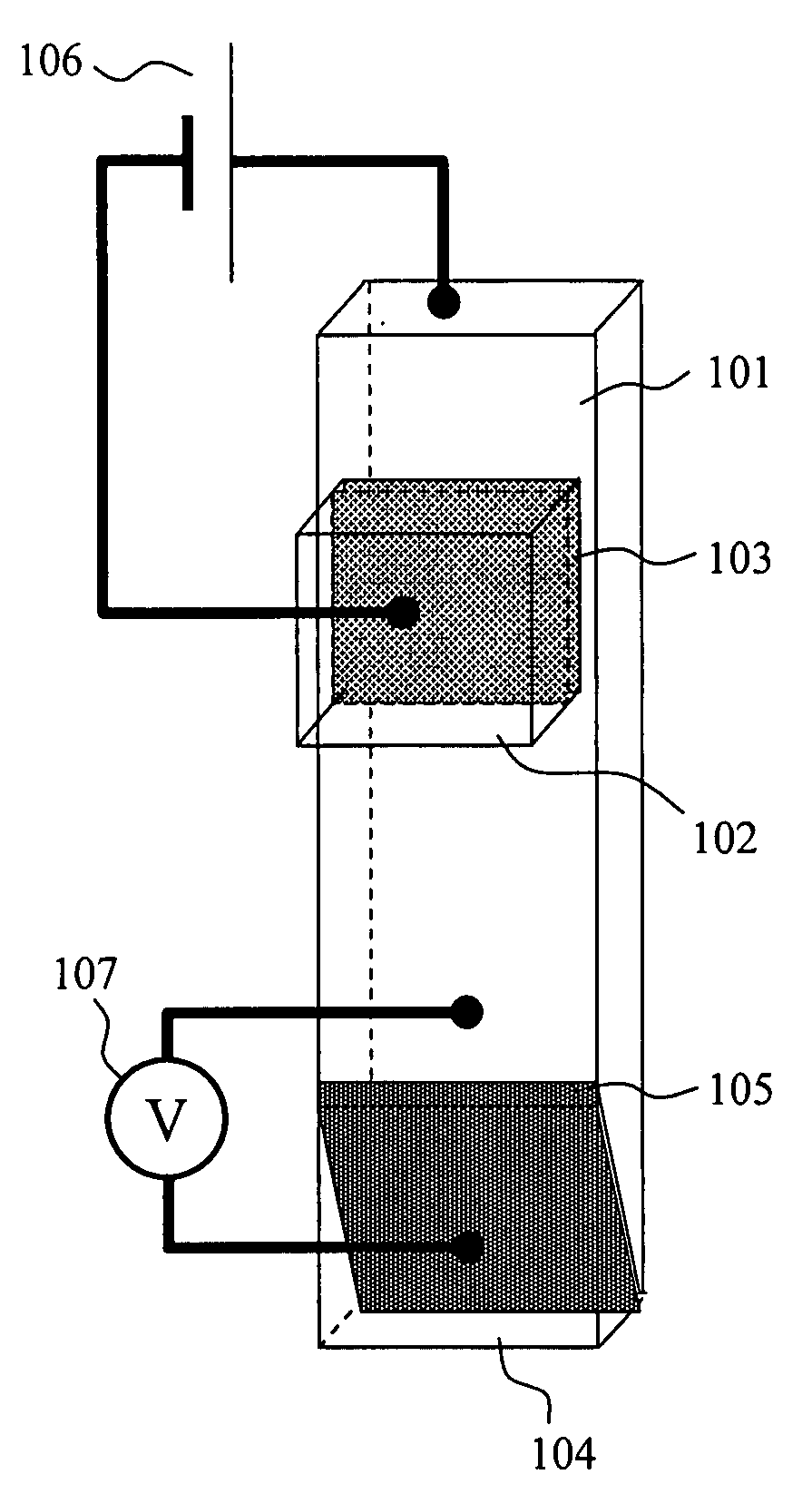
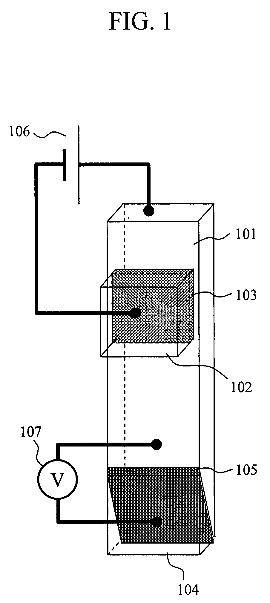
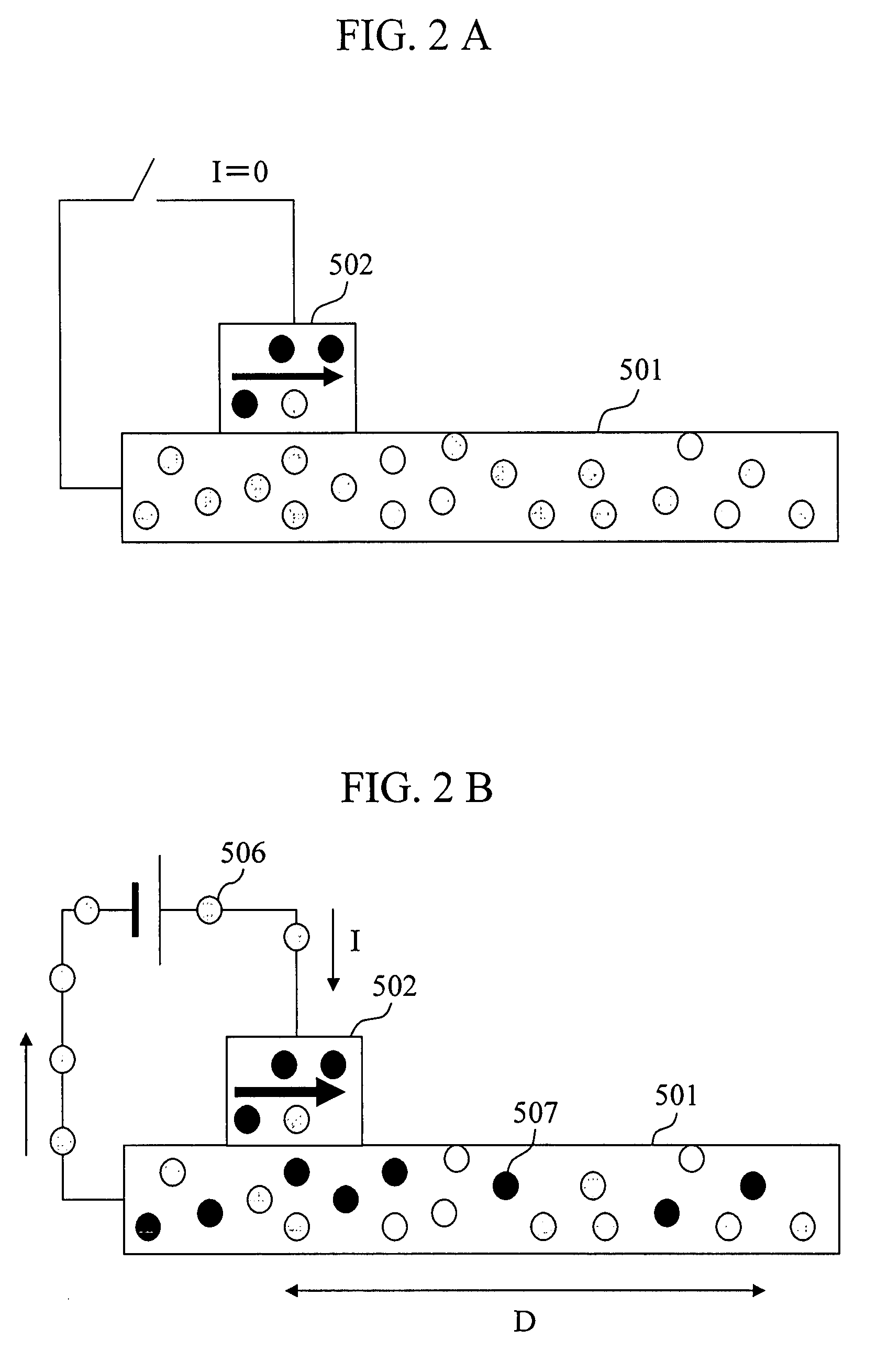
[0010]In the present invention, a magnetic body constituting a magnetic free layer is formed on the end surface of a non-magnetic electrode layer wherein spin polarized electrons are accumulated facing a medium. By this element structure, the volume of the magnetic body constituting the magnetic free layer can be maintained to be at least a certain volume even if the read gap distance is narrowed, and magnetic noise can be suppressed.
[0012]According to the present invention, a magnetic read head wherein element resistance can be more easily controlled than conventional magnetic read heads, a magneto resistive ratio is high, effective to elevating resolution power, and having large output can be obtained. By using such a magnetic read head, a magnetic read-write system having a surface recording density exceeding 1000 Gb / in2 can be realized.

Problems solved by technology

Since the device is basically equipped with a barrier layer in the current path, it is estimated to be affected by shot noise as in TMR.

Method used


Image

  • Magnetic read head and magnetic read write system
  • Magnetic read head and magnetic read write system
  • Magnetic read head and magnetic read write system

Examples


embodiment

[0052]A film of a device was formed on a commonly used substrate, such as a SiO2 substrate and a glass substrate (including a magnesium oxide substrate, a GaAs substrate, an AlTiC substrate, a SiC substrate, an Al2O3 substrate, and the like) using a film forming method, such as in-vacuo sputtering and molecular beam epitaxy (MBE). For example, in the case of RF sputtering, the film was formed in an Ar atmosphere under a gas pressure of about 0.05 to 1 Pa and a power of 50 to 1000 W. As a base material on which the device was formed, the above-described substrate was directly used, or the substrate on which insulating films or suitable base metal films were formed was used.

[0053]As an example, a method for fabricating a device wherein a magnetic pinned layer 102 contacts a non-magnetic electrode layer 101 via a barrier layer 103, and a magnetic free layer 104 is disposed between the non-magnetic electrode layer 101 and the substrate surface 301 represented by a device shown in FIG. 7...


PUM


Abstract

To provide a magnetic head that is suited for high recording density magnetic read and write, and has little noise. A magnetic pinned layer is formed on a non-magnetic electrode layer via a first insulating layer, and a magnetic free layer is formed on a medium-side plane of the non-magnetic electrode layer via a second insulating layer. A circuit for flowing current between the non-magnetic electrode layer and the magnetic pinned layer via the first insulating layer, and a circuit for measuring voltage between the non-magnetic electrode layer and the magnetic free layer are connected to the magnetic free layer. The medium-side plane on which the magnetic free layer is formed may be a plane substantially parallel to the surface of the medium, or may be a plane tilted from the surface of the medium.

Description

CLAIM OF PRIORITY[0001]The present application claims priority from Japanese application JP 2007-013816 filed on Jan. 24, 2007, the content of which is hereby incorporated by reference into this application.BACKGROUND OF THE INVENTION[0002]1. Field of the Invention[0003]The present invention relates to a magnetic read head and magnetic read write system equipped with a magnetoresistive element.[0004]2. Background Art[0005]In the market of magnetic read write systems, the improvement of recording density exceeding the annual rate of 40% has been required, and also in corresponding magnetic read write heads, the improvement of performance for both read and write functions has been required. Among these, it is important for magnetic read heads to satisfy three technical problems: the improvement of sensitivity elevating technology, the improvement of track width reducing technology, and the improvement of read gap distance reducing technology.[0006]In recent years, studies and device d...

Claims


Application Information

Patent Timeline
IPC IPC(8): G11B5/33
CPCG11B5/3903Y10T428/11G11B5/398
Inventor TAKAHASHI, HIROMASAYAMADA, MASAKI
Owner HITACHI LTD
Learn More