Light-emitting device and apparatus having the same

Inactive Publication Date: 2006-09-21
CANON KK
View PDF9 Cites 22 Cited by
  • Summary
  • Abstract
  • Description
  • Claims
  • Application Information

AI Technical Summary

Benefits of technology

[0011] It is an object of the present invention to provide a light-emitting device which enables efficient use of luminous flux from a light source with a simple and inexpensive structure and achieves a desired light emission characteristic (for example, a light distribution characteristic).
[0012] It is another object of the present invention to provide a light-emitting device which enables efficient use of luminous flux from a plurality of light sources with a simple and inexpensive structure, achieves a desired light emission characteristic (for example, a light distribution characteristic), and allows an additional use as an illumination means or a display means.

Problems solved by technology

In such macro photography, the use of a typical illumination apparatus (a light-emitting device) provided for a camera, for example at an upper portion thereof, causes disadvantages such as a failure to illuminate uniformly a necessary irradiation area resulting from part of the illumination light being blocked by a lens barrel, and an unnatural image including a dark shadow on one side of an object.
In the illumination apparatus proposed in Japanese Patent Laid-Open No. 2004-23412, however, the use of a number of generally expensive optical fibers increases the cost of the illumination apparatus or the like, or no optical member provided for controlling light emerging from the optical fibers makes it impossible to achieve a desired light distribution characteristic.
In other words, an optical system is provided for each of the light sources, so that a number of parts are required for illumination and display to need large space and the resulting cellular phone is inevitably expensive.

Method used


Image

  • Light-emitting device and apparatus having the same
  • Light-emitting device and apparatus having the same
  • Light-emitting device and apparatus having the same

Examples


embodiment 1

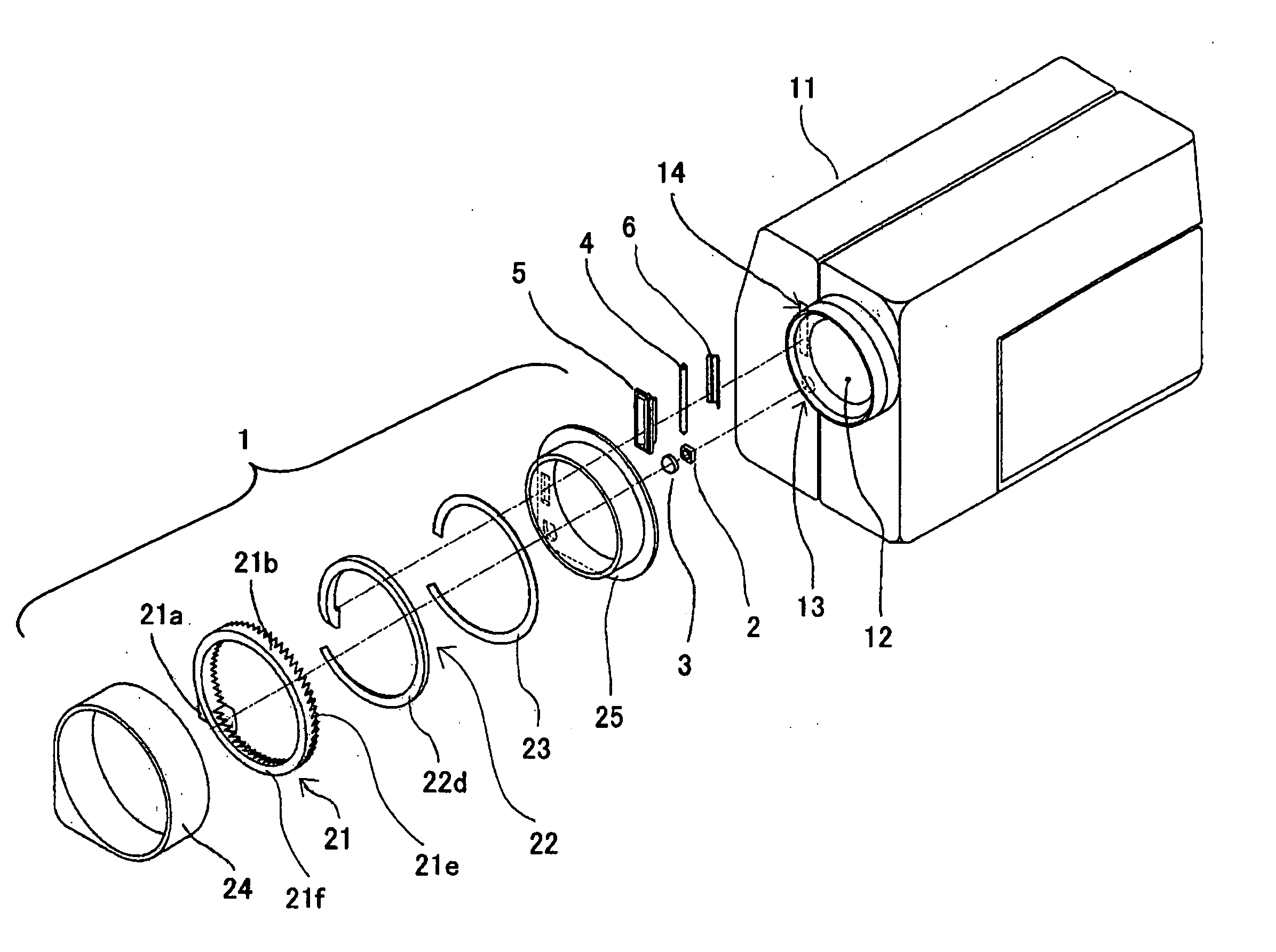
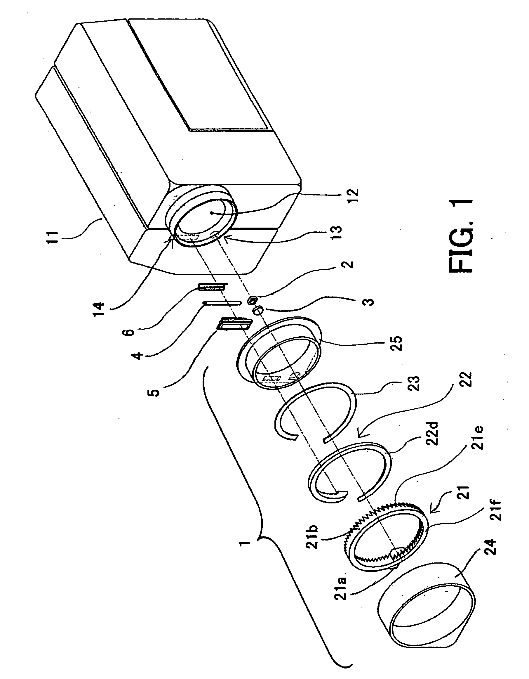
[0051] FIGS. 1 to 9 show a ring light adapter for macro photography serving as a light-emitting device which is Embodiment 1 of the present invention. In Embodiment 1, the ring light adapter is removably mounted around an image-taking lens barrel in an image-taking apparatus such as a video camera.

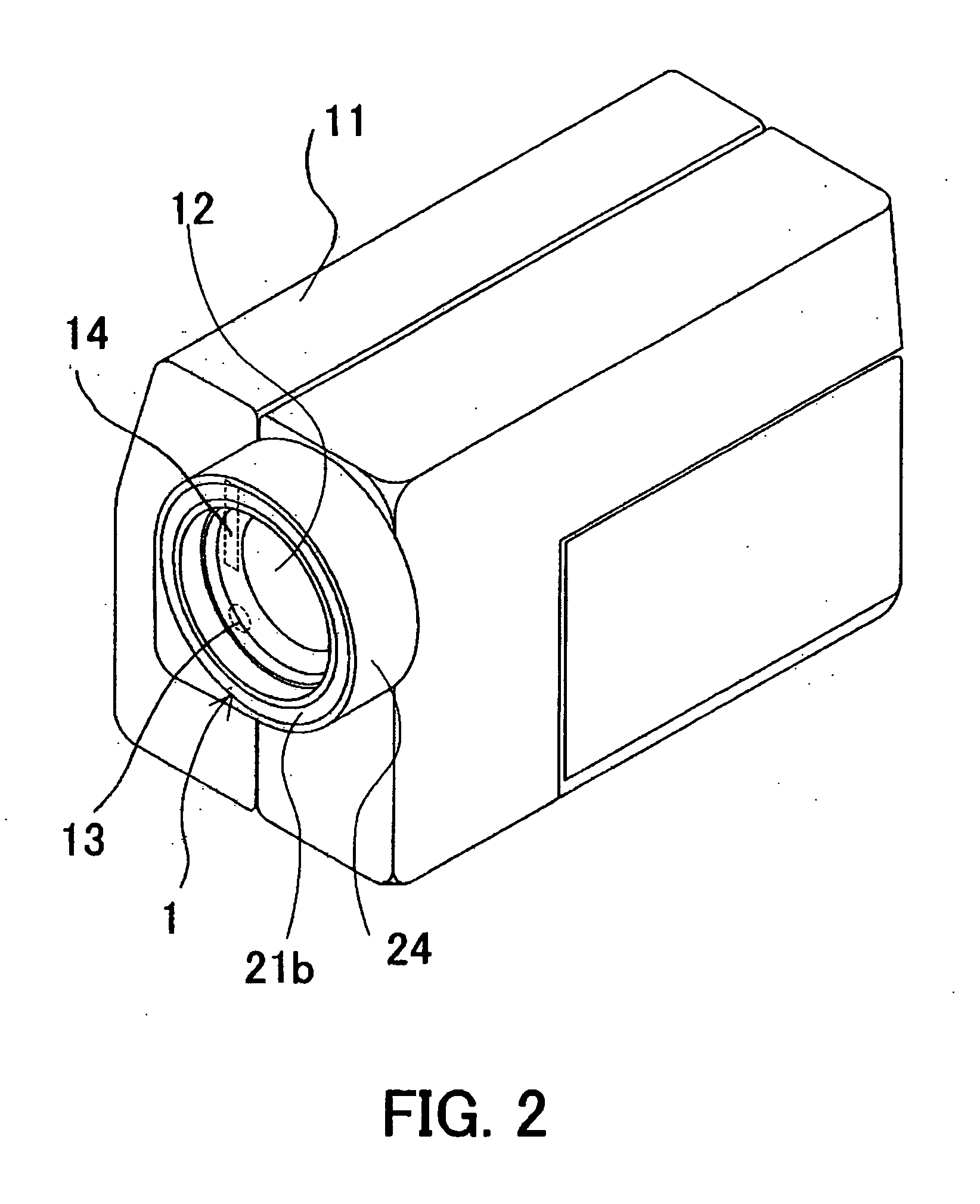
[0052]FIG. 1 is a perspective view showing a main optical system of the ring light adapter (hereinafter referred to as a ring light optical system). FIG. 2 is a perspective view showing the video camera on which the ring light adapter is mounted. FIG. 3 is a front view of the video camera. FIG. 4 is a partial section view showing the video camera.

[0053] As shown in FIGS. 1 and 2, a light emitter 13 and a light emitter 13 and 14 each for emitting light which is to enter the ring light adapter of Embodiment 1 are disposed close to an image-taking lens barrel 12 in a video camera body 11.

[0054] In FIGS. 1 and 2, reference numeral 1 shows the ring light adapter. The video camera body 11 has...

embodiment 2

[0114] FIGS. 10 to 13 show a ring light for macro photography which is Embodiment 2 of the present invention. Embodiment 2 is a variation of Embodiment 1, and the following description will be focused on differences from Embodiment 1. The components identical to those in Embodiment 1 are designated with the same reference numerals in Embodiment 1 and detailed description thereof is omitted.

[0115]FIG. 10 is a section view showing a ring portion of a ring light optical system developed in the circumferential direction in the ring light for macro photography of Embodiment 2 and also shows a light ray tracing diagram of luminous flux emitted from an LED 2. FIG. 11 is a section view showing the ring portion of the ring light optical system developed in the circumferential direction and also shows a light ray tracing diagram of luminous flux emitted from an arc tube 4. FIGS. 12 and 13 are enlarged views of part of the section view (a portion B) in FIG. 11. FIG. 12 shows only the shape of...

embodiment 3

[0126] FIGS. 14 to 19 show a ring light for macro photography which is Embodiment 3 of the present invention. Embodiment 3 is a variation of Embodiment 1.

[0127]FIG. 14 is a front view of a ring portion in a ring light optical system of the ring light for macro photography in Embodiment 3 when viewed from the direction of an emergence surface. FIG. 15 shows a light ray tracing diagram of representative luminous flux from a flashlight emitter added to the ring light optical system in FIG. 14. FIG. 16 shows a light ray tracing diagram of representative luminous flux from an LED light emitter added to the ring light optical system in FIG. 14. FIG. 17 is a section view of the ring portion of the ring light optical system developed in the circumferential direction. FIG. 18 shows a light ray tracing diagram of representative luminous flux from the flashlight emitter added to FIG. 17. FIG. 19 shows a light ray tracing diagram of representative luminous flux from the LED light emitter added...


PUM


Abstract

A light-emitting device is disclosed which enables efficient use of luminous flux and achieves a desired light emission characteristic. The light-emitting device has an optical member which has an emergence surface and a plurality of optical portions, each of the optical portions including a first surface which directs light incident thereon to the emergence surface. The plurality of first surfaces are inclined on the same side with respect to the emergence surface. The light-emitting device also has a light guiding member which directs light from a light source to the plurality of optical portions from one side of a direction in which the plurality of optical portions are arranged.

Description

BACKGROUND OF THE INVENTION [0001] The present invention relates a light-emitting device for use in various apparatuses such as image-taking apparatuses including a digital still camera and a video camera, and camera-equipped cellular phones. [0002] Some of image-taking apparatuses such as a video camera and a digital still camera have a capability to take an image of an object (or subject) at an extremely close range from an image-taking lens (a macro photography capability). [0003] In such macro photography, the use of a typical illumination apparatus (a light-emitting device) provided for a camera, for example at an upper portion thereof, causes disadvantages such as a failure to illuminate uniformly a necessary irradiation area resulting from part of the illumination light being blocked by a lens barrel, and an unnatural image including a dark shadow on one side of an object. [0004] Thus, an illumination apparatus has been proposed in which a ring-shaped light emergence portion ...

Claims


Application Information

Patent Timeline
IPC IPC(8): F21V33/00F21K2/00F21V5/00H01L33/58H01L33/60
CPCG02B6/0018G02B6/002G02B6/003G02B6/0038G02B6/0076G02B6/008G03B15/03G03B2215/0539H04N5/2256H04N23/56
Inventor TENMYO, YOSHIHARU
Owner CANON KK
Why Eureka
Try Eureka