Timing recovery in a parallel channel communication system
Active Publication Date: 2006-09-21
SEAGATE TECH LLC
View PDF22 Cites 46 Cited by
Summary
Abstract
Description
Claims
Application Information
AI Technical Summary
This helps you quickly interpret patents by identifying the three key elements:
Problems solved by technology
Method used
Benefits of technology
Benefits of technology
[0060] It is to be understood that even though numerous characteristics and advantages of various embodiments of the invention have been set forth in the foregoing description, together with details of the structure and function of various embodiments of the invention, this disclosure is illustrative only, and changes may be made in detail, especially in matters of structure and arrangement of parts within the principles of the present invention to the full extent indicated by the broad general meaning of the terms in which the appended claims are expressed. For example, the particular elements may vary depending on the particular application for the timing recovery system while maintaining substantially the same functionality without departing from the scope and spirit of the present invention. In addition, although the preferred embodiment described herein is directed to a storage media system for data, it will be appreciated by those skilled in the art that the teachings of the present invention can be applied to other types of digital communication channels, without departing from the scope and spirit of the present invention.
Problems solved by technology
As the number of parallel channels increases in newer, larger disc drives, the signal-to-noise ratios (SNR's) are degraded, and the multiple timing recovery circuits consume increasing amounts of electrical power and circuit resources in the disc drive.
Furthermore, one or more of the timing recovery circuits may not gain synchronization at all due to the degradation of SNR.
The read / write channel of a disc drive is just one example of a general problem of communication channels with increasing numbers of parallel data channels that require timing recovery, but that are increasingly consuming excess electrical power and computing resources to perform timing recovery functions in a receiver portion of the communication channel.
Method used
Image
Click on the blue label to locate the original text in one second.
Reading with bidirectional positioning of images and text.
Examples
first embodiment
[0026]FIG. 3 illustrates a block diagram of a parallel channel timing recovery circuit 300 that includes a sampling control output 302 based on a composite 304 of discrete time signal samples ri(k), r2(k), r3(k) . . . rM(k). The timing recovery circuit 300 receives multiple simultaneous data channels y1(t), y2(t), y3(t) . . . yM(t) from parallel read heads or other parallel data channels.
[0027] A number M of multiple prefilters 306, 308, 310 . . . 312 are provided in the timing recovery circuit 300. The prefilters 306, 308, 310, 312 each receive one of the data channels y1(t), y2(t), y3(t) . . . yM(t) and provides a corresponding prefilter output r1(t), r2(t), r3(t) . . . rM(t). The prefilters 306, 308, 310, 312 are preferably bandpass filters with a passband corresponding to the bandwidth of the data expected at the data channels y1(t), y2(t), y3(t) . . . yM(t). The prefilters 306, 308, 310, 312 filter out noise. The prefilters 306, 308, 310, 312 can also limit the bandwidth of the...
second embodiment
[0033]FIG. 4 illustrates a block diagram of a parallel channel timing recovery circuit 400 that includes a sampling control output 302 based on a composite 304 of discrete time signal samples. Reference designations used in FIG. 4 that are the same as reference designations used in FIG. 3 identify the same or similar features. In FIG. 4, the sampling filters 314, 316, 318, 320 of FIG. 3 comprise sampling switches 414, 416, 418, 420 that are controlled by the sampling control output 302. In other respects, the recovery circuit 400 in FIG. 4 is similar to the recovery circuit 300 in FIG. 3.
third embodiment
[0034]FIG. 5 illustrates a block diagram of a parallel channel timing recovery circuit 500 that includes a sampling control output based on a composite of discrete time signal samples. Reference designations used in FIG. 5 that are the same as reference designations used in FIGS. 3-4 identify the same or similar features.
[0035] In FIG. 5, the joint timing and data detector 340 comprises a plurality of independent detectors 550, 552, 554, 556 and a composite timing errordetector (C-TED) circuit 560 that extracts timing error estimates from the parallel incoming signals ri(k) and their corresponding decision outputs {circumflex over (α)}i(k) from the detectors 550, 552, 554, 556.
[0036] The C-TED 560 receives input from the multiple sampled waveforms ri(k) as well as the decision outputs {circumflex over (α)}i(k) from the detectors (or preambles during the acquisition phase) to compute the current timing error estimate 304. The output 304 from the C-TED 560 is then low-pass filtered ...
PUM
Abstract
A parallel channel timing recovery circuit. The parallel timing recovery circuit comprises multiple prefilters receiving parallel channel outputs and providing prefilter outputs. Multiple sampling filters receive the prefilter outputs and provide multiple discrete time signal samples. A self-timing circuit has multiple inputs receiving the multiple discrete time signal samples. The self-timing circuit provides a sampling control output to the sampling filters. The sampling control output is based on a composite of the multiple discrete time signal samples. Each of the sampling filters generates a discrete time signal sample based on the sampling control output and the prefilter outputs.
Description
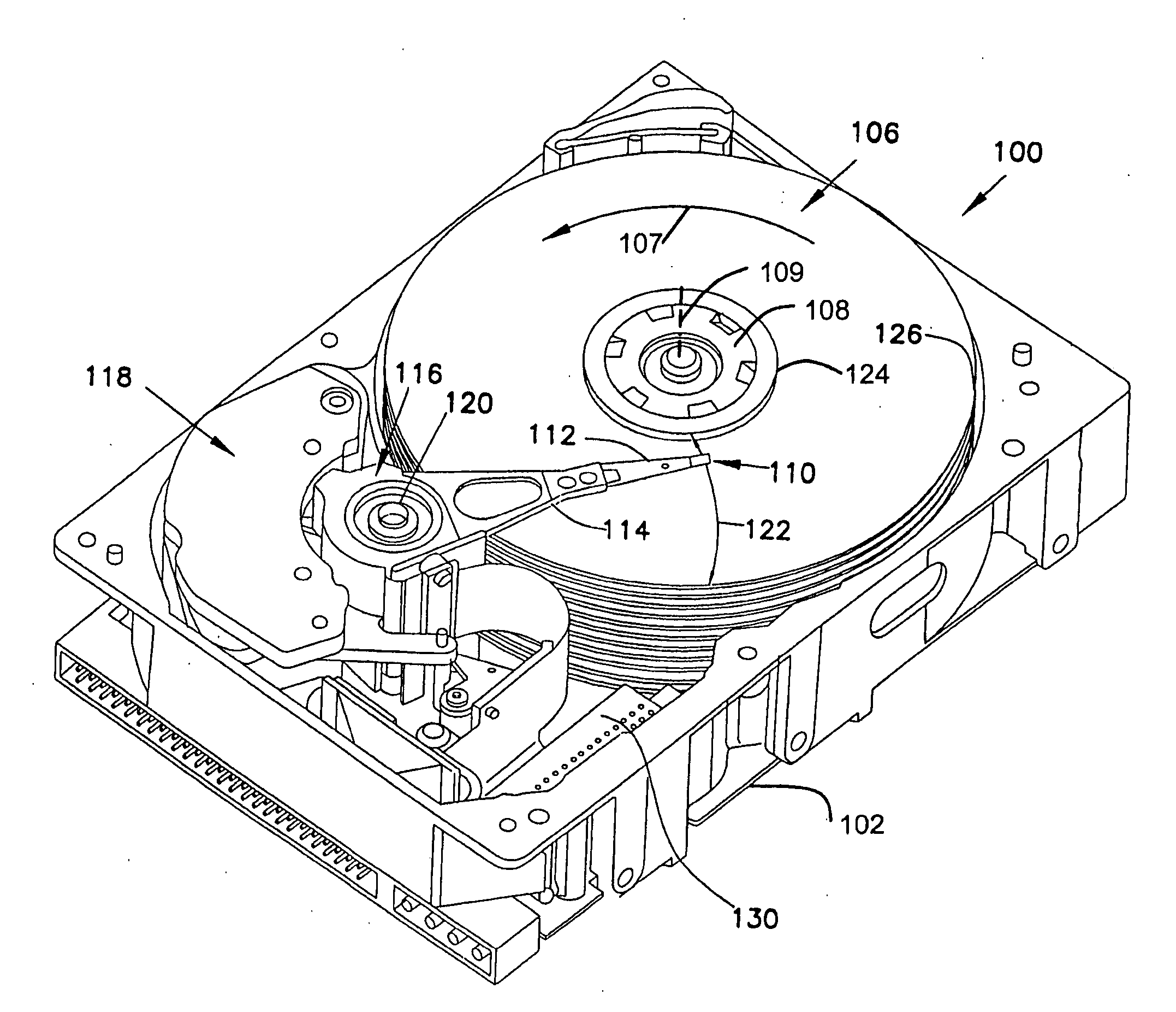
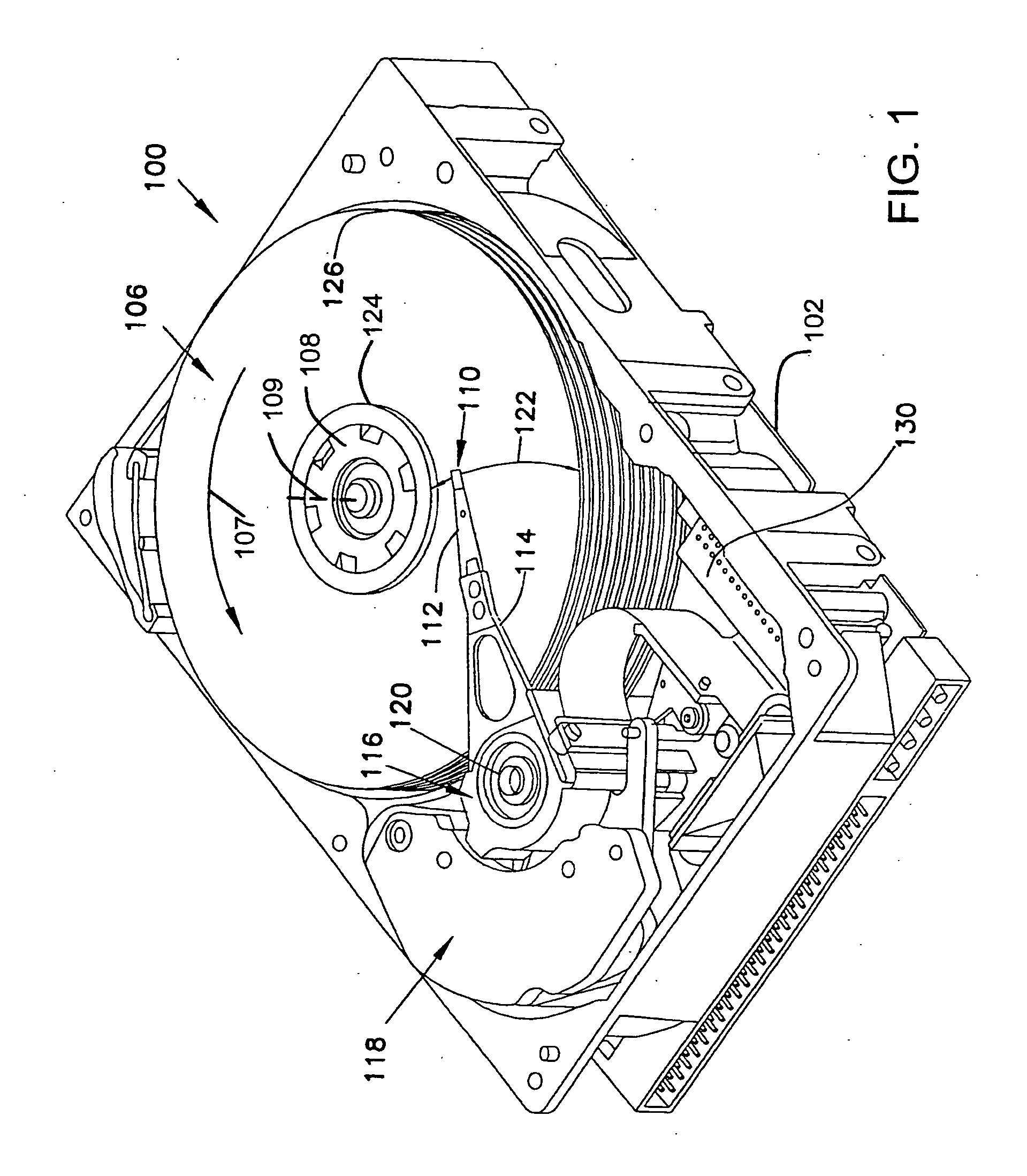
FIELD OF THE INVENTION [0001] The present invention relates generally to parallel communication channels, and more particularly but not by limitation to data storage devices with multiple read channels. BACKGROUND OF THE INVENTION [0002] In data storage devices such as disc drives, data is read from a disc by a read operation that involves a mechanical scanning motion of a disc moving relative to a read head. The read data is initially in synchronization with the mechanical motion during writing and needs to be resynchronized as the data is read processed by a computer. This process of resynchronization is accomplished by a timing recovery circuit. [0003] In some disc drives, there is an array of multiple read heads that are reading data simultaneously (i.e., in parallel) on multiple read channels. Each of the multiple channels includes a timing recovery circuit. As the number of parallel channels increases in newer, larger disc drives, the signal-to-noise ratios (SNR's) are degrade...
Claims
Application Information
Patent Timeline
Application Date:The date an application was filed.
Publication Date:The date a patent or application was officially published.
First Publication Date:The earliest publication date of a patent with the same application number.
Issue Date:Publication date of the patent grant document.
PCT Entry Date:The Entry date of PCT National Phase.
Estimated Expiry Date:The statutory expiry date of a patent right according to the Patent Law, and it is the longest term of protection that the patent right can achieve without the termination of the patent right due to other reasons(Term extension factor has been taken into account ).
Invalid Date:Actual expiry date is based on effective date or publication date of legal transaction data of invalid patent.

