Sound system, method for controlling the sound system, and sound equipment

Active Publication Date: 2006-09-21
YAMAHA CORP
View PDF2 Cites 16 Cited by
  • Summary
  • Abstract
  • Description
  • Claims
  • Application Information

AI Technical Summary

Problems solved by technology

Further, because the sound signal processing section in each of the sound units supplies the adjoining sound unit with the sound signal with an internal time delay duly compensated for, the entire system can be caused to function as a single sound apparatus.

Method used


Image

  • Sound system, method for controlling the sound system, and sound equipment
  • Sound system, method for controlling the sound system, and sound equipment
  • Sound system, method for controlling the sound system, and sound equipment

Examples


Embodiment Construction

[Construction]

[0020]

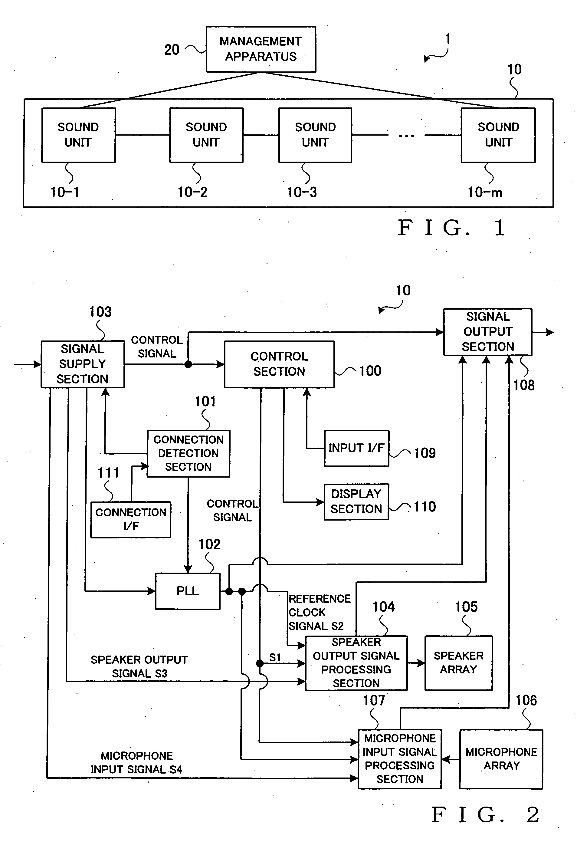
[0021]FIG. 1 is a block diagram showing a general setup of a sound system 1 in accordance with an embodiment of the present invention. As shown, the sound system 1 comprises a set of m (m represents an arbitrary natural number) sound units 10 (10-1, 10-2, 10-3, . . . , 10-m;) connected with one another, and a management apparatus 20 for controlling all of the sound units 10. Each of the sound units 10, except for two sound units located in opposite ends of the sound unit set, is connected with adjoining sound units, so that the sound units 10 constitute a chained-together sound unit set. Only the two sound units 10-1 and 10-m located in the opposite ends of the sound unit set are connected to the management apparatus 20. In the following description, the sound units 10-1, 10-2, 10-3, . . . , 10-m are assumed to be similar in function and will be referred to simply as “sound units 10” unless it is necessary to distinguish among the individual sound units.

[0022]F...


PUM


Abstract

In each sound unit, when connection with another sound unit is detected, an input control signal is supplied to a control section and then supplied to the adjoining sound unit. Input clock signal is supplied to a PLL section, and an output clock signal from the PLL section is supplied to the adjoining sound unit. Input speaker output signal and microphone input signal are supplied to a speaker output signal processing section and microphone input signal processing section, respectively. The speaker output signal processing section performs predetermined signal processing on an input signal to output the resultant processed signal to a speaker array, and then performs internal delay compensation processing on the signal to output the resultant processed signal to the adjoining sound unit. The microphone input signal processing section calculates a sum of the input signal and sums of delayed signals of outputs from the microphone array and then performs internal delay compensation processing on the signal to output the resultant processed signal to the adjoining sound unit.

Description

BACKGROUND OF THE INVENTION [0001] The present invention relates generally to techniques for connecting a plurality of pieces of sound equipment to cause the connected pieces of equipment to function together as a single unit. [0002] In the field of speaker array systems each comprising a plurality of speaker units, there has been known a technique for imparting a sound signal with time delays corresponding to phase differences and providing the resultant delayed sound signals to the individual speakers such that the signals agree in phase only at a desired position (focal point) to which the sound is to be conveyed, so as to form a high sound pressure region (i.e., sound beam) extending toward the focal point or a spot-shaped high sound pressure region (i.e., sound spot) produced at and around the focal point (e.g., Japanese Patent Application Laid-open Publication No. HEI-06-205496 which corresponds to U.S. Pat. No, 5,953,432). Further, in the field of microphone array systems eac...

Claims


Application Information

Patent Timeline
Patent Type & Authority Applications(United States)
IPC IPC(8): H04B3/00
CPCH04R1/403H04R1/406H04R3/005H04R3/12H04R2201/403H04R2203/12H04R2227/003H04R2420/03H04R2420/07H04S7/00H04S7/40
Inventor ISHIBASHI, TOSHIAKISONE, TAKURO
Owner YAMAHA CORP
Why Eureka
Try Eureka