Imaging apparatus and method for controlling display device

Inactive Publication Date: 2006-09-21
CANON KK
View PDF6 Cites 147 Cited by
  • Summary
  • Abstract
  • Description
  • Claims
  • Application Information

AI Technical Summary

Benefits of technology

[0017] The present invention is directed to an imaging and/or displaying technique that can automatically detect an object from photographed image data and can di

Problems solved by technology

In general, the movement of a sports player is very moving (i.e., rapid) and accordingly it is very difficult to find out or track a particular player through an optical finder or on a back monitor of an imaging apparatus.
However, many of the participants in such an event are unknown to the photographer.
Therefore, it is generally difficult for the photographer to check and confirm whether or not all of the participants have be

Method used


Image

  • Imaging apparatus and method for controlling display device
  • Imaging apparatus and method for controlling display device
  • Imaging apparatus and method for controlling display device

Examples


first embodiment

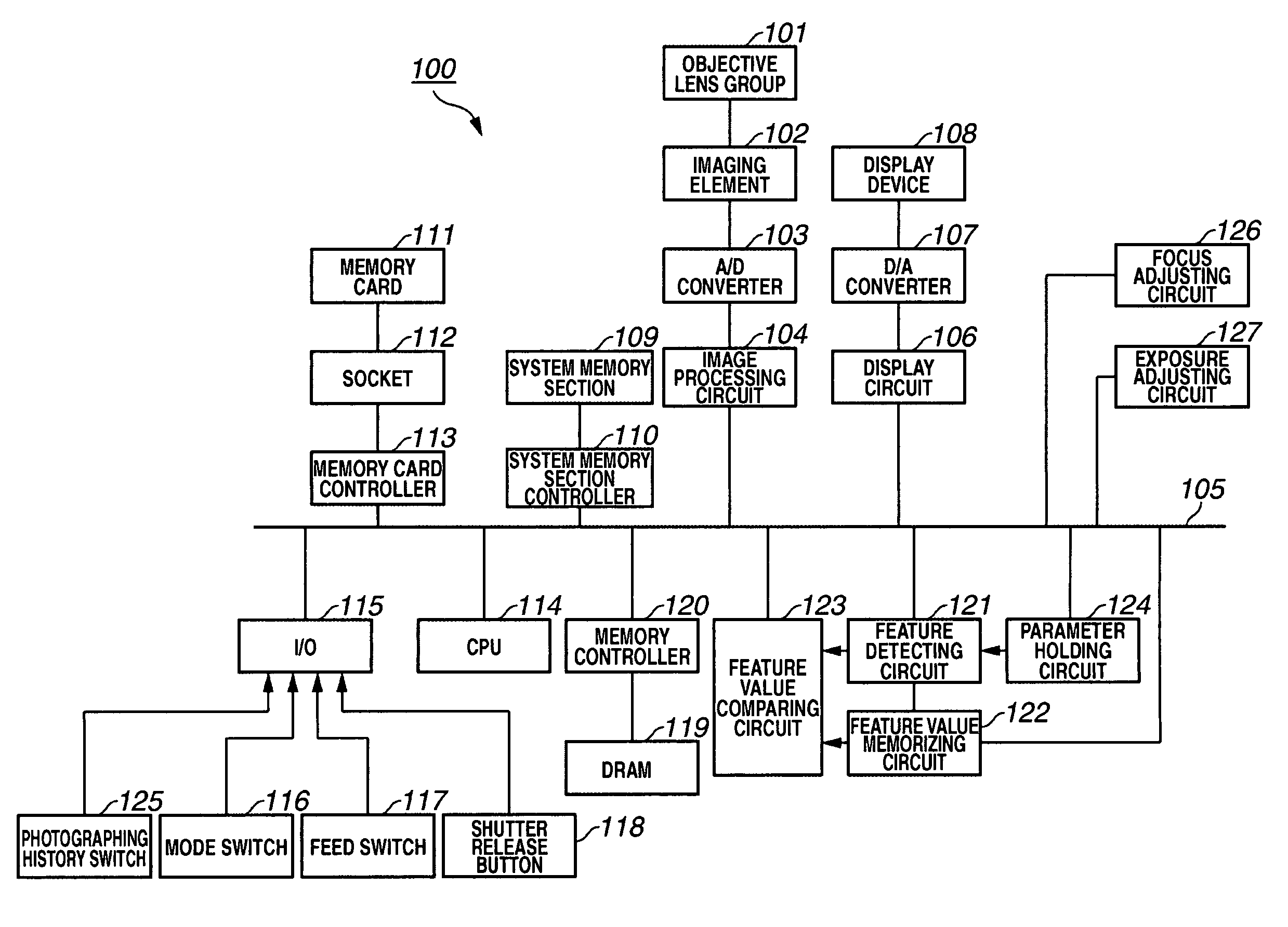
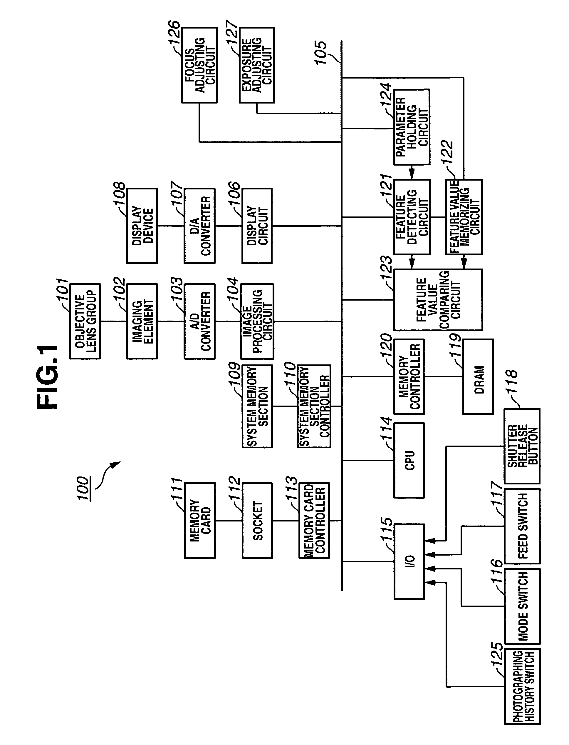
[0040]FIG. 1 shows the arrangement of an imaging apparatus 100 in accordance with a first embodiment. In the present embodiment, the imaging apparatus 100 is an electronic still camera.

[0041] In FIG. 1, an objective lens group 101 is an assembly of lenses for forming an object image on an imaging element 102. The imaging element 102, such as a charge-coupled device (CCD), has a photoelectric conversion function and can convert the object image obtained through the objective lens group 101 into analog image data. An analog-digital (A / D) converter 103 receives the analog image data sent from the imaging element 102 and converts the analog image data into digital image data. An image processing circuit 104 can apply various imaging processing to the digital image data converted by the A / D converter 103 to produce display-oriented image data and recording-oriented image data.

[0042] A data bus 105 can transfer the image data. A display circuit 106 can process the display-oriented image...

second embodiment

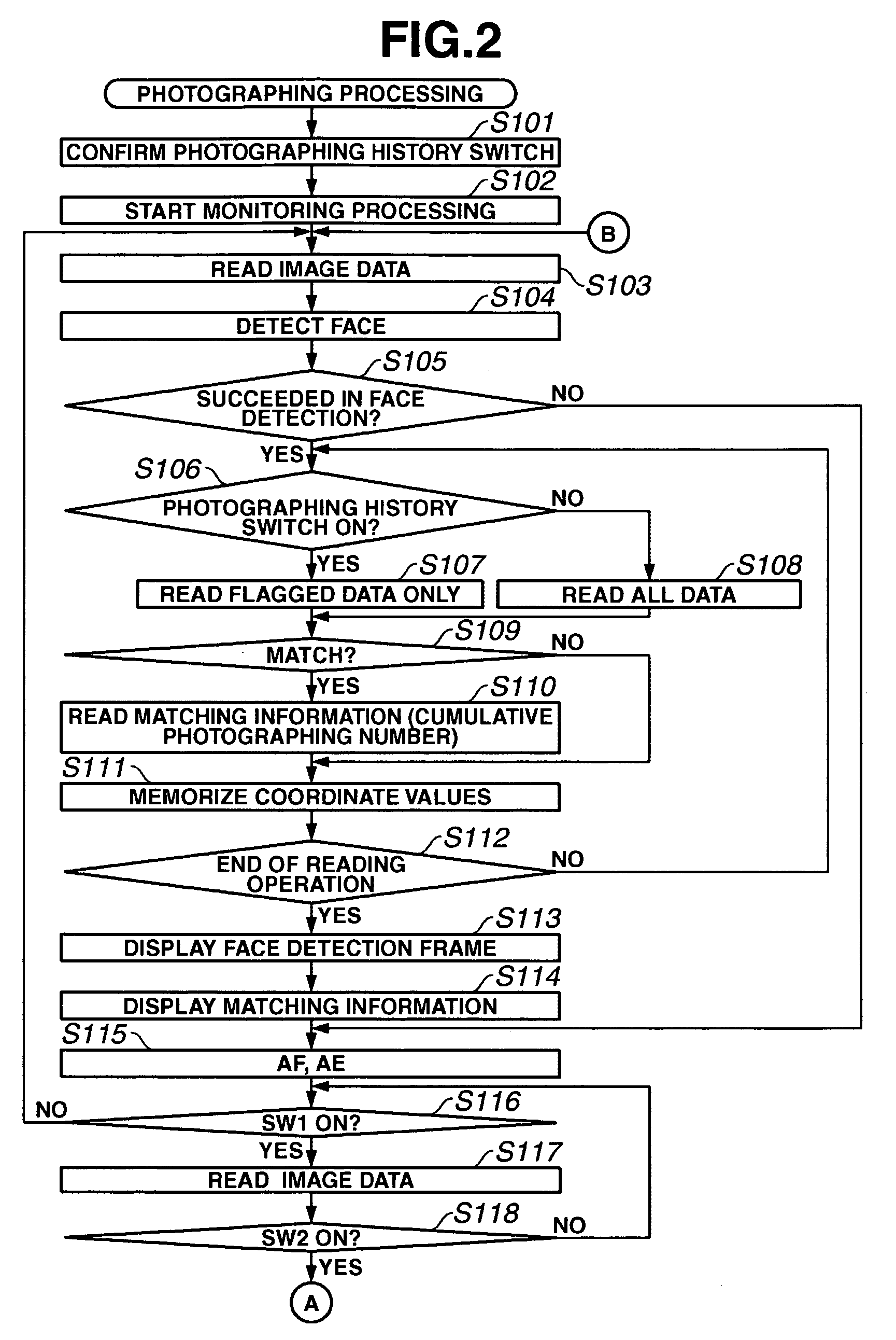
[0117] Next, another photographing processing of the imaging apparatus 100 will be described with reference to the flowchart shown in FIG. 5. The flowchart shown in FIG. 5 is different from the flowchart shown in FIG. 2 in that the face detection is not constantly performed during the monitoring processing and is performed only when there is any change in the detected object.

[0118] In FIG. 5, the steps identical with those shown in FIG. 2 are denoted by the same reference numerals.

[0119] When a user sets a photographing mode, the CPU 114 confirms the condition of the photographing history switch 125 in step S101.

[0120] In step S102, the CPU 114 produces display-oriented image data based on an output of the imaging element 102 and starts the monitoring processing for controlling the display device 108 to display a moving or time-varying image of the detected object.

[0121] In step S103, the imaging element 102 performs the photoelectric conversion to output analog image data. The ...

third embodiment

[0126] Next, another photographing processing of the imaging apparatus 100 will be described with reference to the flowchart shown in FIG. 6. The third embodiment (i.e., the flowchart shown in FIG. 6) is different from the first or second embodiment in that the face detection result gives no effects on the focus adjustment processing and the exposure adjustment processing.

[0127] When a photographing mode is set by a user through the mode switch 116, the CPU 114 starts the operation according to the flowchart shown in FIG. 6.

[0128] In step S101, the CPU 114 confirms the condition of the photographing history switch 125. When the photographing history switch 125 is in an ON state, it means that the operation is in the history period.

[0129] In step S102, the CPU 114 produces display-oriented image data based on an output of the imaging element 102 and starts the monitoring processing for displaying a moving or time-varying image of a detected object on the display device 108.

[0130]...


PUM


Abstract

An imaging apparatus automatically detects an object and displays information on a display device based on a comparison between detected data and memorized (stored) data. The imaging apparatus includes a detecting circuit and a memorizing circuit. The detecting circuit detects the object based on the image data produced from an output of an imaging element and calculates a feature value representing a feature of the detected object. The memorizing circuit memorizes the feature value calculated by the detecting circuit. A feature value calculated by the detecting circuit based on the image data displayed on the display device is compared with the feature value memorized in the memorizing circuit. The display device displays information relating to the comparison result.

Description

BACKGROUND OF THE INVENTION [0001] 1. Field of the Invention [0002] The present invention relates to an imaging apparatus and a method for controlling a display device. [0003] 2. Description of the Related Art [0004] There are conventional techniques capable of detecting a face image from an entered image using a method that can automatically detect a face region by detecting a characteristic portion or a flesh color portion of an object face from object image data. [0005] For example, the conventional technique discussed in Japanese Patent Application Laid-open No. 2004-013871 can register particular reference image data and can determine whether or not newly entered image data agrees with the reference image data. [0006] For example, the conventional technique discussed in Japanese Patent Application Laid-open No. 09-251534 can identify a face region by calculating a correlation value between the image data of a pre-registered face and the image data of an object face. [0007] Furt...

Claims


Application Information

Patent Timeline
IPC IPC(8): G03B17/18
CPCG03B13/30H04N5/23212H04N5/23293H04N2101/00H04N23/675H04N23/61H04N23/635
Inventor SAGA, YOSHIHIRO
Owner CANON KK
Why Eureka
Try Eureka