Liquid crystal composition and liquid crystal display device
Inactive Publication Date: 2006-09-21
JNC CORP +1
View PDF3 Cites 22 Cited by
Summary
Abstract
Description
Claims
Application Information
AI Technical Summary
This helps you quickly interpret patents by identifying the three key elements:
Problems solved by technology
Method used
Benefits of technology
Benefits of technology
[0033] An advantage of the invention is to provide a liquid crystal composition that satisfies many characteristics among the characteristics such as a wide temperature range of a nematic phase, a suitable optical anisotropy, a negatively large dielectric anisotropy, and a large specific resistance, and in particular, a liquid crystal composition that satisfies the characteristics and simultaneously has a small optical anisotropy and a low minimum temperature of a nematic phase, and preferably approximately −20° C. or less. Another advantage of the invention is to provide a liquid crystal display device containing the composition, and the liquid crystal display device has a large voltage holding ratio and is driven by an active matrix (AM) mode suitable for a VA mode, an IPS mode and so forth.
[0034] As a result of earnest investigations made by the inventors in view of the problems associated with the conventional techniques, it has been found that a liquid crystal composition containing a liquid crystal compound having a specific structure, in which two hydrogens adjacent to each other on a benzene ring are replaced by chlorine and fluorine, and another liquid crystal compound having a specific structure has a wide temperature range of a nematic phase, a suitable optical anisotropy, a negatively large dielectric anisotropy, and a large specific resistance, and a liquid crystal display device containing the composition has a large voltage holding ratio. Thus, the invention has been completed.
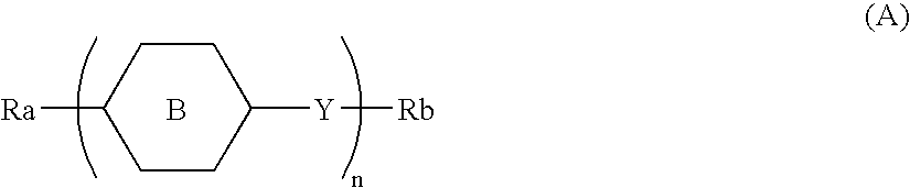
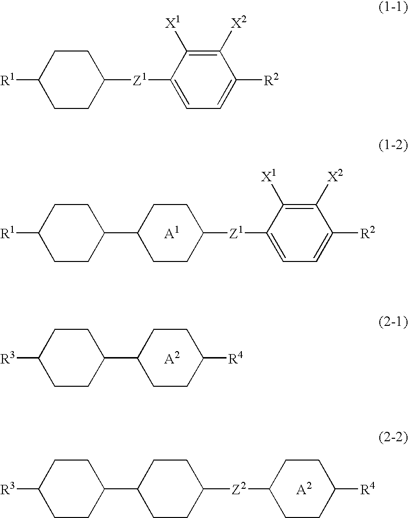
[0036] 1. A liquid crystal composition having a negative dielectric anisotropy and comprising a first component comprising at least one compound selected from a group of compounds represented by formulas (1-1) and (1-2) and a second component comprising at least one compound selected from a group of compounds represented by formulas (2-1) and (2-2): wherein, independently in each formula,
[0037] R1 is alkyl having 1 to 8 carbons or alkenyl having 2 to 8 carbons;
[0038] R2 is alkyl having 1 to 8 carbons or alkoxy having 1 to 7 carbons;
[0039] R3 is alkyl having 1 to 8 carbons or alkenyl having 2 to 8 carbons;
Problems solved by technology
However, the compound having a hydrogen on a benzene ring replaced by fluorine exemplified in JP H02-503441 A / 1990 is poor in compatibility with other liquid crystal compounds in a low temperature range, and in the case where a liquid crystal composition is formed with the compound, the composition cannot be used in a low temperature range in some cases.
However, a liquid crystal composition containing a compound having 2,3-difluorophenylene cannot have a small optical anisotropy (Δn) (for example, 0.07 or less) in some cases.
However, a composition containing the compound does not have a high clear point and has a large viscosity.
Method used
Image
Click on the blue label to locate the original text in one second.
Reading with bidirectional positioning of images and text.
Examples
example 1
[0254] The following composition was prepared, and the characteristic values thereof were measured by the aforementioned methods.
NI = 69.3° C.; Tc ≦−20° C.; Δn = 0.073; Δε = −2.7; VHR-1 = 99.4%
[0255] The composition of Example 1 had a low minimum temperature of ≦−20° C. and a small optical anisotropy Δn as compared to Comparative Example 1, and had a large voltage holding ratio.
example 2
[0256] The following composition was prepared, and the characteristic values thereof were measured by the aforementioned methods.
NI = 69.0° C.; Tc ≦−20° C.; Δn = 0.086; Δε = −3.0; VHR-1 = 99.2%
[0257] The composition of Example 2 had a low minimum temperature of ≦−20° C. as compared to Comparative Example 1, and had a large voltage holding ratio.
example 3
[0258] The following composition was prepared, and the characteristic values thereof were measured by the aforementioned methods.
NI = 70.0° C.; Tc ≦−20° C.; Δn = 0.075; Δε = −3.4; VHR-1 = 99.2%
[0259] The composition of Example 3 had a low minimum temperature of ≦−20° C. as compared to Comparative Example 1, and had a large voltage holding ratio.
PUM
Abstract
What are provided include a liquid crystal composition that satisfies many characteristics among the characteristics such as a wide temperature range of a nematic phase, a suitable optical anisotropy, a negatively large dielectricanisotropy, and a large specific resistance, a liquid crystal composition that satisfies the characteristics and simultaneously has a small optical anisotropy and a low minimum temperature of a nematic phase, and preferably approximately −20° C. or less, and a liquid crystaldisplay device containing the composition. The liquid crystal composition has a negative dielectricanisotropy and contains a first component containing a liquid crystal compound containing, as one of the groups having a ring structure, a benzene ring having two hydrogens adjacent to each other replaced by fluorine and chlorine, and a second component containing a liquid crystal compound having a specific structure containing no halogen, and the liquid crystal display device contains the liquid crystal composition.
Description
BACKGROUND OF THE INVENTION [0001] 1. Field of the Invention [0002] The invention relates to a liquid crystal composition and a liquid crystal display device. More specifically, the invention relates to a liquid crystal composition suitable for use in an active matrix (AM) device, and a liquid crystal display device containing the composition. [0003] 2. Related Art [0004] A liquid crystal display device (which is a generic term for a liquid crystal display panel and a liquid crystal display module) utilizes optical anisotropy, dielectricanisotropy and so forth of a liquid crystal composition, and as an operating mode of the liquid crystal display device, such various modes have been known as a phase change (PC) mode, a twisted nematic (TN) mode, a super twisted nematic (STN) mode, a bistable twisted nematic (BTN) mode, an electrically controlled birefringence (ECB) mode, an optically compensated bend (OCB) mode, an in-plane switching (IPS) mode, a vertical alignment (VA) mode, and ...
Claims
Application Information
Patent Timeline
Application Date:The date an application was filed.
Publication Date:The date a patent or application was officially published.
First Publication Date:The earliest publication date of a patent with the same application number.
Issue Date:Publication date of the patent grant document.
PCT Entry Date:The Entry date of PCT National Phase.
Estimated Expiry Date:The statutory expiry date of a patent right according to the Patent Law, and it is the longest term of protection that the patent right can achieve without the termination of the patent right due to other reasons(Term extension factor has been taken into account ).
Invalid Date:Actual expiry date is based on effective date or publication date of legal transaction data of invalid patent.

