Compact enclosure for SONET multiplexer cards and SONET multiplexer card having front panel access to electrical and optical connectors

a sonet multiplexer and enclosure technology, applied in the direction of electrical apparatus casing/cabinet/drawer, coupling device connection, instruments, etc., can solve the problems of reducing the flexibility of the shelf, and reducing the space for adding equipment with new features

Inactive Publication Date: 2006-09-21
HUBBELL INC
View PDF30 Cites 18 Cited by
  • Summary
  • Abstract
  • Description
  • Claims
  • Application Information

AI Technical Summary

Problems solved by technology

Problems with existing equipment managing DS3 traffic, however, are numerous.
For example, DS3 hierarchy-based equipment requires more bay and shelf space in CO, RT, cell sites and other locations where equipment space is already a limited commodity, where bays and shelves are already crowded (e.g., many shelf card slots are filled with a card), and where room to add equipment with new features is very limited or essentially nonexistent.
Dedicating specific portions of the shelf to specific service types reduces the flexibility of the shelf, and typically leaves wasted shelf space for any given application.
In equipment locations were space is limited, it can be difficult for human operators to gain access to the backs of card slots in a shelf of an equipment bay.
The Fujitsu multplexer 10 is not easily set up or provisioned.
Since it is not designed to be compatible with any one particular system, it provides hundreds of choices to the user and must be substantially configured by a user operating a provisioning application on a computer (e.g., a personal computer or PC) before it can even run data through it.
Further, after such a lengthy and involved configuration phase, the unit may not be subsequently easily reprovisioned to accommodate a change in the configured data paths.
This aspect of the Fujitsu multplexer 10 renders it very cumbersome.
Also, to use the Fujitsu multplexer 10 in different applications such as a drop or drop and continue (e.g., ring) application requires more plug-in units, which increases cost, and requires more set up and provisioning.
Providing redundancy of optical paths can present a problem where there is limited equipment space since additional circuit packs are used in competing SONET multiplexers.
This redundant configuration is disadvantageous over a system having only a single optical path between two multiplexers, and therefore no redundancy, because it requires twice the equipment space and twice the cost for the extra two multiplexers.
Further, the redundant system is less reliable in terms of the increased likelihood for electronics failure or equipment failure due to heat, for example, due to the additional multiplexer electronics.
The limitations of the known systems discussed above also render those systems difficult to use in 3rd Generation (3G) wireless services.
In particular, the costs and complexities of delivering the known DS3 systems to cell cites have limited their ability to be deployed in 3G systems.
For example, severely limited cabinet or hut space would require expensive new enclosures and power supplies to run the known DS3 systems.
Furthermore, because 3G systems require upgrades to numerous cell cites, costs related to the time consuming provisioning and interconnect of traditional SONET equipment expand rapidly.
Alternative fiber optic systems that can be used are either exorbitantly expensive or limited to point-to-point rather than efficient drop-and-continue topologies.
In addition, future growth has been limited by large up-front equipment investments or products that are limited to supporting only 3 DS3s.

Method used


Image

  • Compact enclosure for SONET multiplexer cards and SONET multiplexer card having front panel access to electrical and optical connectors
  • Compact enclosure for SONET multiplexer cards and SONET multiplexer card having front panel access to electrical and optical connectors
  • Compact enclosure for SONET multiplexer cards and SONET multiplexer card having front panel access to electrical and optical connectors

Examples


Embodiment Construction

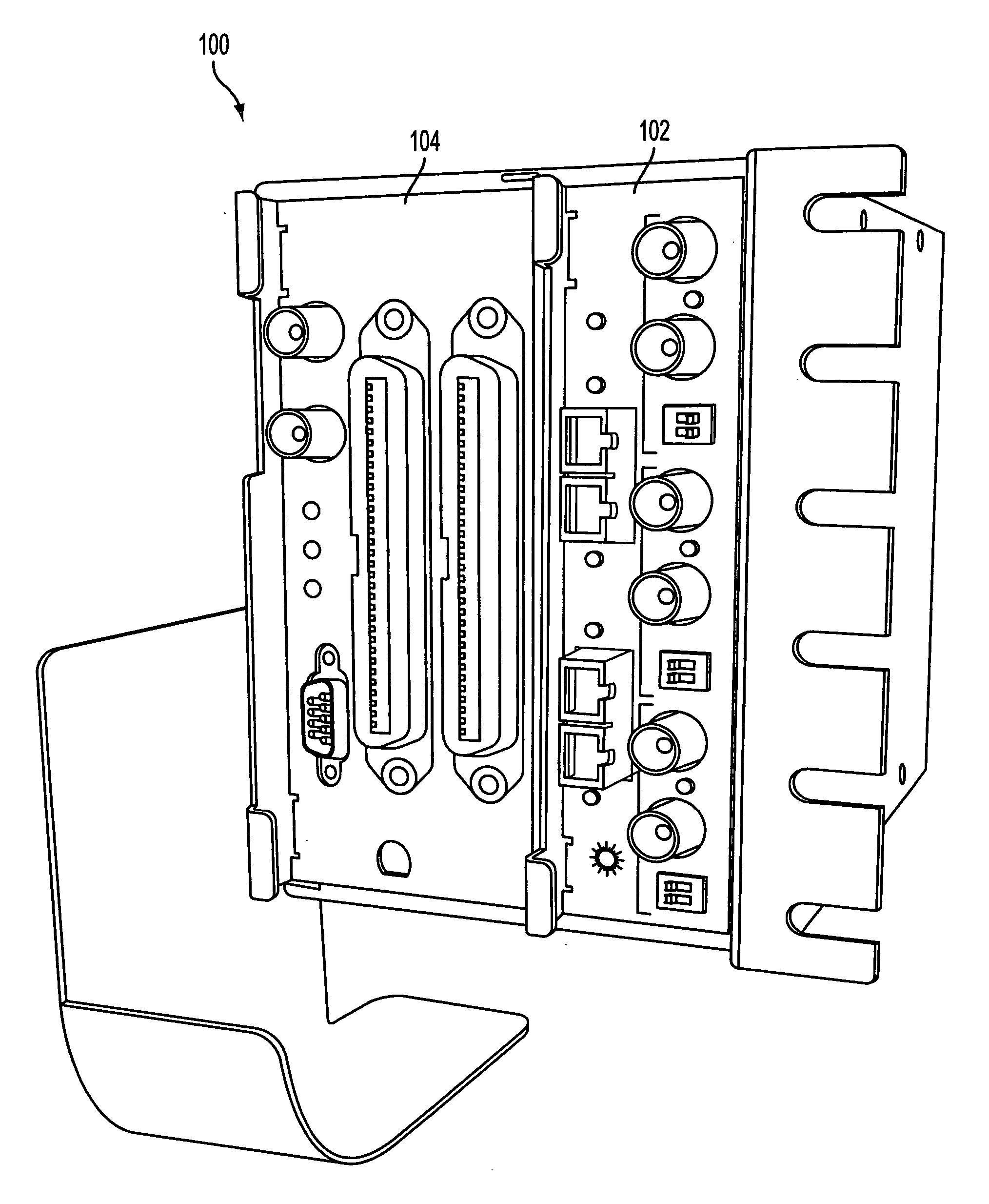
[0055]FIG. 3 is a perspective view of a reduced-size assembly 100 for mounting SONET and other multiplexing equipment to achieve DS3 and other multiplexing capabilities according an embodiment of the present invention. As described in more detail below, the assembly 100 is capable of receiving different combinations of modules, such as, but not limited to, O3-3D3, O3-3D3P, DS3 Express, D3-14D1, D3-28D1, and WDM mod depending on the type of application and the types of interfaces required.

[0056] In the example shown in FIG. 3, a O3-3D3 module 102 and a D3-28D1 module 104 are removably installed in the assembly 100. As shown in FIG. 4, the assembly 100 includes an enclosure assembly 106 that can be made of aluminum, anodized steel or any other suitable material. In this example, the enclosure assembly 106 includes an enclosure 108 on top of which is mounted a fan 110 for cooling the modules inserted in the enclosure 108. The enclosure 108 has a cable fiber management assembly 112 for...


PUM


Abstract

A reduced size multiplexer and, in particular, a reduced size SONET multiplexer module is provided for use in a reduced size enclosure. The SONET multiplexer module has electrical and optical connectors on its faceplate to provide ease in access without having to remove the SONET multiplexer from the enclosure. The SONET multiplexer circuit is configured in a standard Type 400 mechanics circuit board arrangement. The SONET multiplexer module therefore can be inserted into an enclosure in a direction opposite to that in which the coaxial connector projects from the face plate, so that the coaxial connector remains freely accessible outside of the enclosure when the SONET multiplexer module is fully loaded into the enclosure. Coaxial cables and optical fibers can thus be easily coupled to the coaxial and optical connectors, respectively, when the SONET multiplexer circuit is fully loaded into the enclosure.

Description

[0001] This application is a continuation of U.S. patent application Ser. No. 10 / 448,463, filed May 30, 2003.CROSS REFERENCE TO RELATED APPLICATIONS [0002] Related subject matters is disclosed in co-pending U.S. patent application of Bruce Lipski et al., filed even date herewith, entitled “Apparatus and Method for Increasing Optical Density of SONET Multiplexer Using Integral Components”(Attorney's File 44783); in co-pending U.S. patent application of Bruce Lipski et al., filed even date herewith, entitled “SONET Multiplexer Having Front Panel Access to Electrical and Optical Connectors and Method for Using Same”(Attorney's File 44784); and in co-pending U.S. patent application of Bruce Lipski et al., filed even date herewith, entitled “Apparatus And Method For Automatic Provisioning of SONET Multiplexer”(Attorneys File 44786); the entire contents of each of these applications being expressly incorporated herein by reference. FIELD OF THE INVENTION [0003] The present invention relat...

Claims


Application Information

Patent Timeline
Patent Type & Authority Applications(United States)
IPC IPC(8): H01R3/00G02B6/44H04J3/16H04J14/02
CPCG02B6/4452G02B6/4453H04J3/1611H04J14/02
Inventor LIPSKI, BRUCEMILLER, GARY M.CORP, DAVID O.
Owner HUBBELL INC
Why Eureka
Try Eureka