Electronic device terminal connector

a technology for electrical devices and terminal connectors, applied in the direction of electromagnetic relay details, coupling device connections, relays, etc., can solve the problem of reducing the likelihood that the wiring operation will be performed incorrectly, and achieve the effect of simplifying the operation of the insulation covering, preventing the insulation from deteriorating, and reducing the amount of insulation coverings

Inactive Publication Date: 2006-09-21
FUJI ELECTRIC FA COMPONENTS & SYST CO LTD
View PDF0 Cites 4 Cited by
  • Summary
  • Abstract
  • Description
  • Claims
  • Application Information

AI Technical Summary

Benefits of technology

[0014] In order to solve the above problems, according to the invention, a terminal connection apparatus for electrical devices is provided in which the terminal connection apparatus has terminal connection conductors for a plurality of phases for bridging terminals of two adjacent electrical devices. The terminal connection conductor has terminal sections at both ends for connection to the terminals of the electrical devices. The terminal connection conductor is U-shaped and the space between the terminal sections is covered by an insulation material. An insulation case, housing the terminal connection conductors, collectively surrounds the terminal connection conductors for a plurality of phases, except for the terminal sections, to provide unitization. This enables the insulation of the terminal connection conductors to be completely protected from the exterior. Also, since each of the terminal connection conductors can be covered with insulation in the minimum range required for interphase insulation, this permits use of a thermal contraction tube to minimize the amount of insulation covering utilized and simplifying the insulation covering operation. Further, the terminal connection conductors for a plurality of phases are connected after having been unitized by the insulation case, which reduces the likelihood that the wiring operation will be performed incorrectly. Further yet, the insulation case may have a box-like shape to collectively house the terminal connection conductors for a plurality of phases, and thus can be widely used regardless of the wiring type (e.g., phase order wiring, phase switching order wiring). Furthermore, the insulation case is sealed by a cover body, thus preventing the insulation from det...

Problems solved by technology

Further, the terminal connection conductors for a plurality of phases are connected after having been uniti...

Method used


Image

  • Electronic device terminal connector
  • Electronic device terminal connector
  • Electronic device terminal connector

Examples


Embodiment Construction

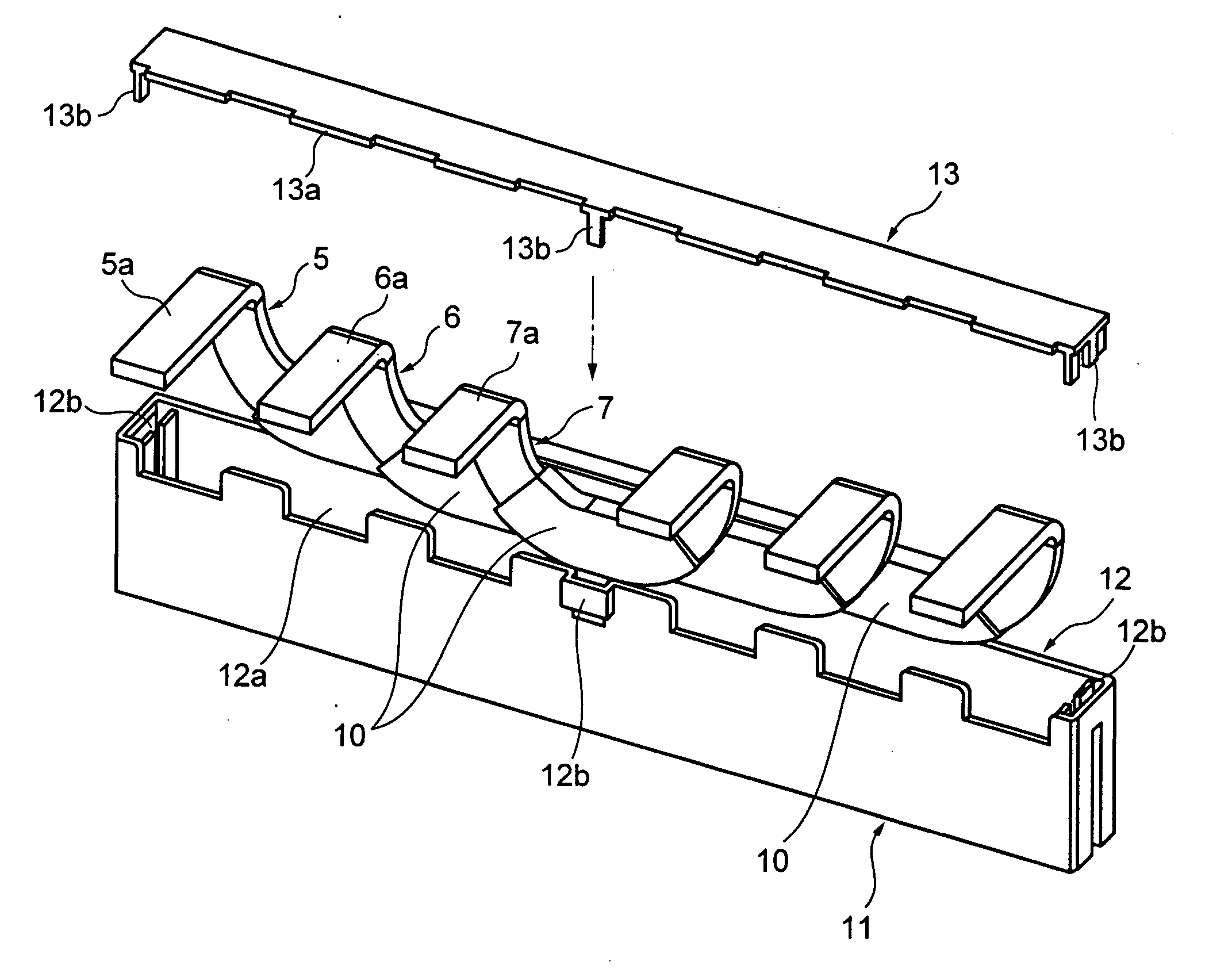
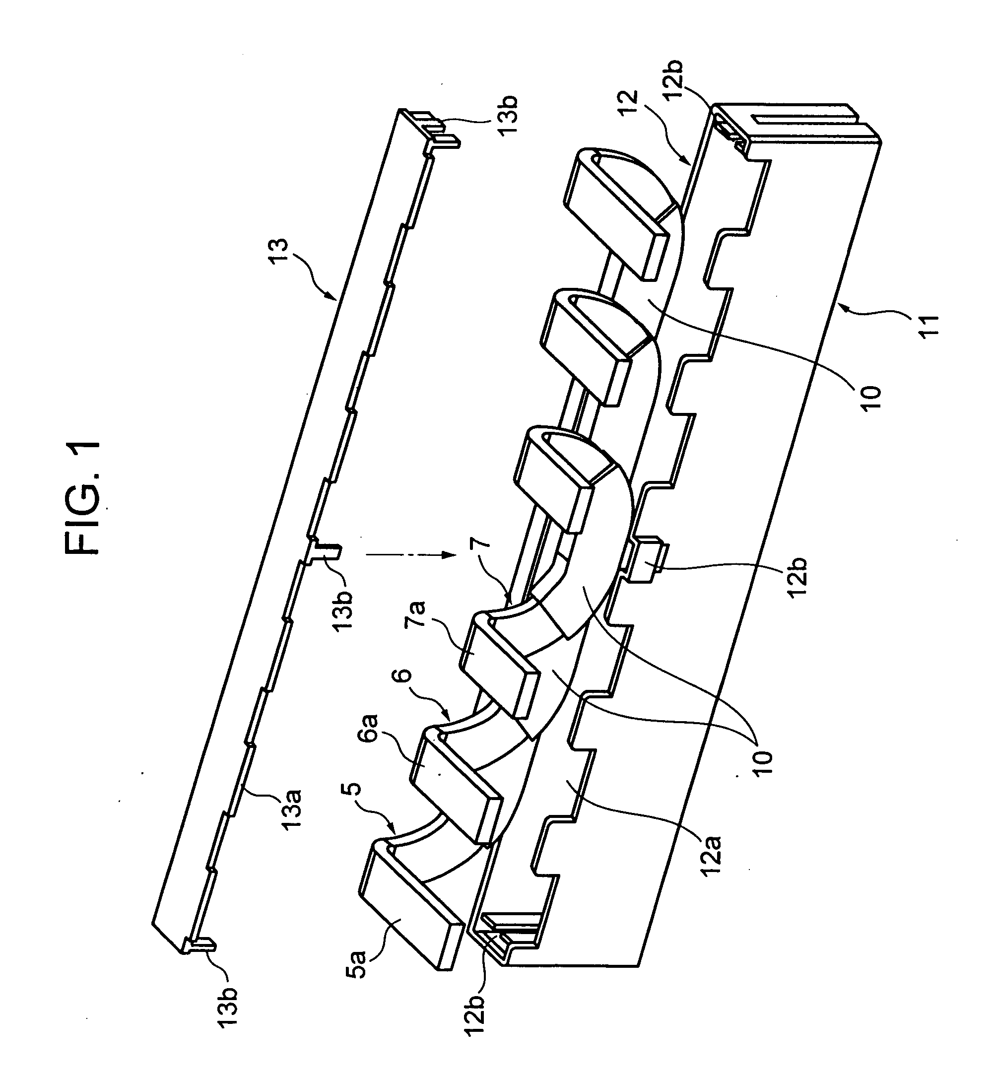
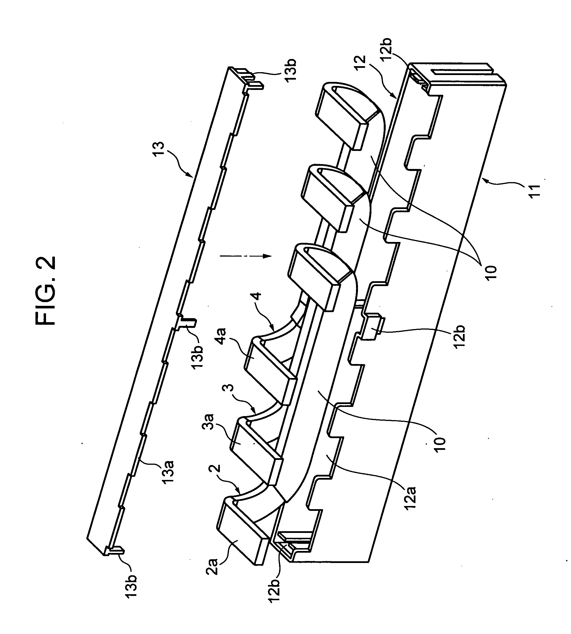
[0026] Hereinafter, with reference to FIGS. 1 to 4B, an embodiment of this invention will be described. FIG. 1 is an exploded perspective view of a terminal connection apparatus of a phase switching connection. FIG. 2 is an exploded perspective view of a terminal connection apparatus of phase order connection. FIG. 3 is a perspective view illustrating the appearance of the apparatus of FIG. 1 or FIG. 2. FIG. 4A is a side view of an electromagnetic contactor for reversible operation using the apparatus of FIG. 1 or FIG. 2. FIG. 4B is the front view. In the drawings, the same components as those of the conventional example are denoted with the same reference numerals.

[0027] In FIG. 1 and FIG. 2, the terminal connection conductors 2 to 7 each consist of a U-shaped conductor pressed out of a plate material and both ends thereof are bent at a right angle to provide terminal sections 2a to 7a. The conductor part, except for the terminal sections 2a to 7a, is covered by an insulation mate...


PUM


Abstract

In a terminal connection apparatus by which the space between terminals, such as the terminals of two adjacent electromagnetic contactors, is bridged by three-phase terminal connection conductors arranged in the order of the phases or in the order of phase switching to realize a motor reversing operation, load switching, power source switching or the like, the three-phase terminal connection conductors are housed in a box-shaped insulation case for unitization. As a result, the terminal connection conductors are collectively surrounded by the insulation case to protect the insulation. At the same time, the terminal connection conductors are connected to an electrical device in a unitized manner, thus preventing wrong wiring operation when they are connected.

Description

BACKGROUND OF THE INVENTION [0001] 1. Field of the Invention [0002] The present invention relates to a terminal connection apparatus for bridging between terminals of neighboring electrical devices (e.g., contactors (relays), on / off devices). [0003] 2. Prior Art [0004] According to a known arrangement, when a motor is normal / reverse-operated, or when one power source is connected to two loads in a switching manner, or when two power sources are connected to one load in a switching manner, two electromagnetic contactors (relays) or two similar on / off devices are provided so as to be physically adjacent to each other, and a terminal connection apparatus is used for bridging the terminals of these devices using terminal connection conductors. FIGS. 5A, 5B and 5C illustrate wiring diagrams of a three-pole electromagnetic contactor in various applications using such a terminal connection apparatus. [0005]FIG. 5A shows the connection in which two electromagnetic contactors 1 are used to p...

Claims


Application Information

Patent Timeline
IPC IPC(8): H01R31/08H01H9/02H01H50/14H01H51/00
CPCH01H9/0264H01R31/085H01H51/005H01H50/14H01R13/516
Inventor TAKAYA, KOUETSUDAIJIMA, HIDEKI
Owner FUJI ELECTRIC FA COMPONENTS & SYST CO LTD
Why Eureka
Try Eureka