
Sterile syringe

a sterile, fluid technology, applied in laboratory equipment, intravenous devices, chemistry apparatus and processes, etc., can solve the problems of high cost, high cost of equipment and acceptable working conditions for staff, and high contamination risk, and achieve the effect of simple and effectiv

Active Publication Date: 2006-09-21
MERCK LIFE SCI AB
View PDF8 Cites 36 Cited by
  • Summary
  • Abstract
  • Description
  • Claims
  • Application Information

AI Technical Summary

Benefits of technology

[0014] An object of the present invention is to provide a syringe of the type stated by way of introduction, which eliminates one of the above drawbacks and risks in a simple and effective manner.
[0017] A further object of the invention is to provide a syringe which is inexpensive and simple to manufacture.
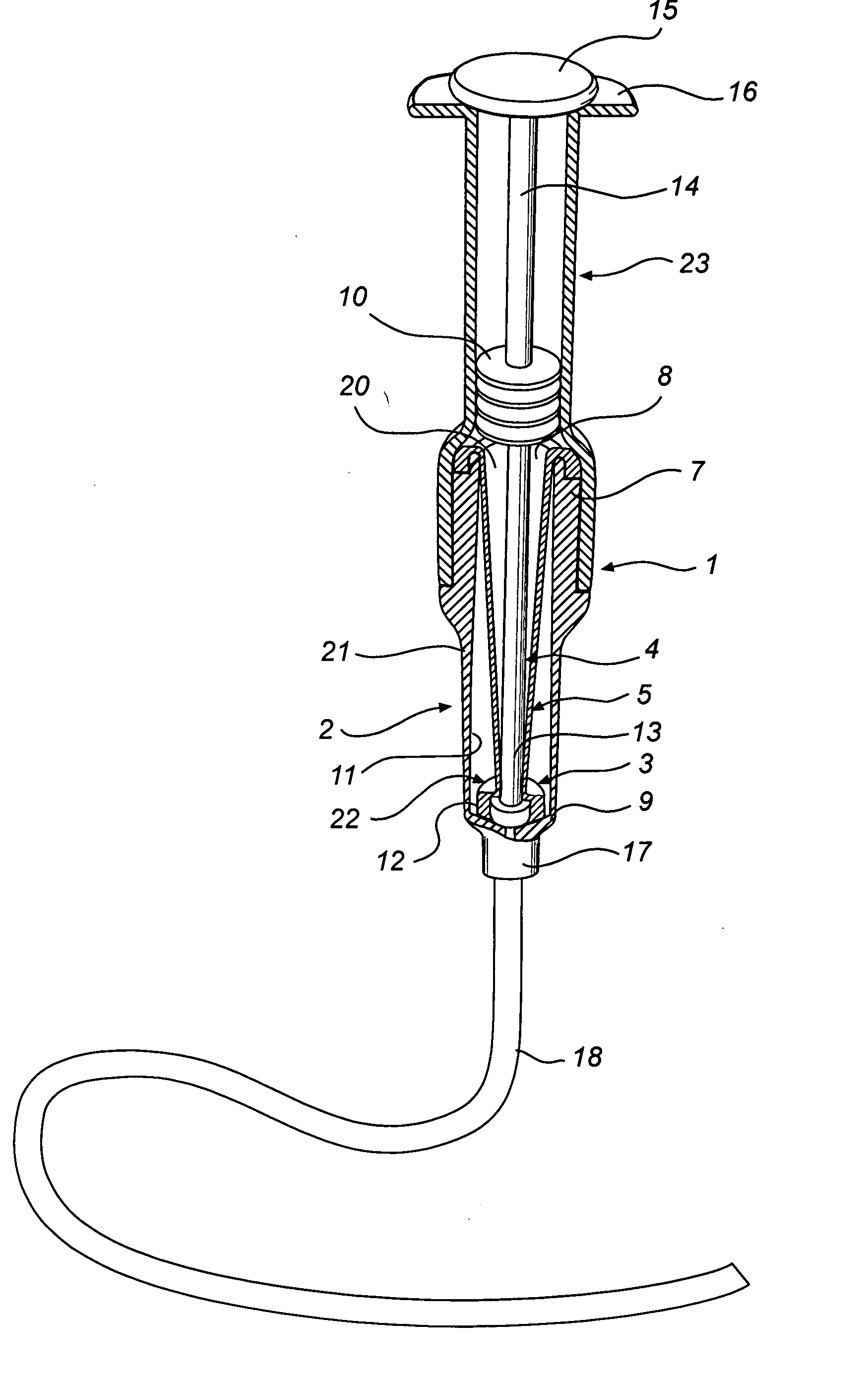
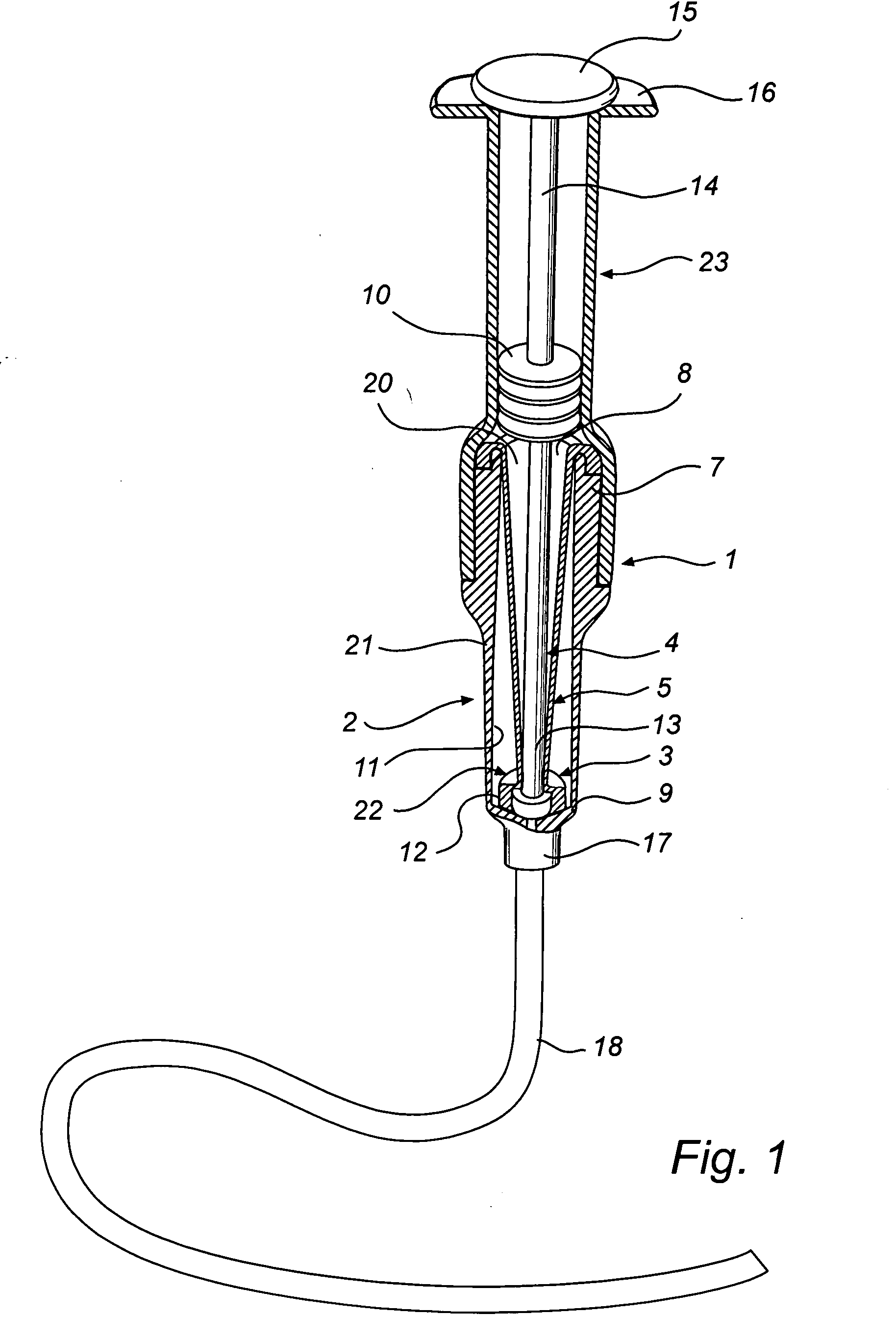
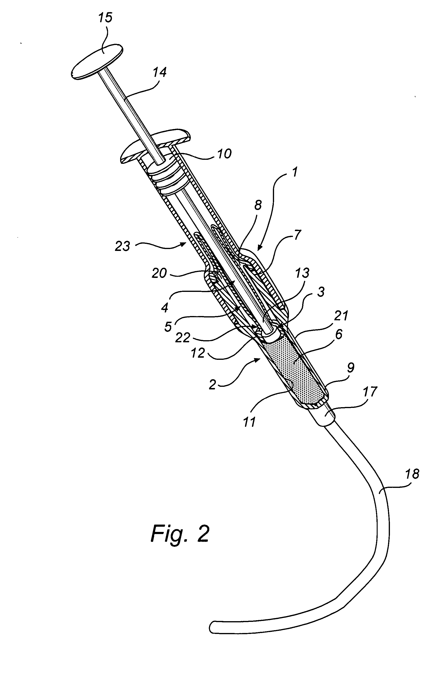
[0019] According to one aspect of the present invention, a syringe for fluid is provided, comprising a cylinder, a piston portion which is arranged in the cylinder and slidable on its inside, and an operating means connected to the piston portion for sliding thereof. The operating means projects from a first end of the cylinder and the cylinder has at a second end an inlet and outlet part for said fluid. A sealing means is connected in a contamination-free manner to the cylinder in the area of its first end and extends into the cylinder to isolate, sealed against contamination, the inside of the cylinder from the environment. In one embodiment, the sealing means is at least connected in a contamination-free manner to the cylinder and extends into the cylinder to isolate, sealed against contamination, the inside of the cylinder from the operating means which can be, for instance, a piston rod. The syringe is preferably intended for sampling of liquids, but of course the present invention can be used in other applications and also for other media, such as gases. The sealing means protects the inside of the cylinder from the environment and the risk of contamination. This is ensured by the sealing means separating the piston rod from the inside of the cylinder, thus forming a chamber isolated from the environment and defined by the cylinder, the sealing means and a piston portion at the inner end of the piston rod. This isolated chamber is presterilised simultaneously with the syringe, after which the chamber remains free of contaminants from the environment outside the syringe.

Problems solved by technology

There is, however, a risk of contamination when one or more media are to be supplied to the process vessel or a sample is to be taken from the process vessel.
Due to this risk of contamination in and around the process vessel, the supply and sampling of the media therefore take place in clean room environment, which requires great investments, expensive equipment and acceptable working conditions for the staff.
In sampling according to prior-art technique, there are problems with false positive results, that is that the medium from which samples are taken is not contaminated but the sample nevertheless indicates contamination.
This is a costly problem since the medium that is being sampled is often expensive and occurs in large volumes.
False positive results are often due to problems with the sampling equipment which may cause contamination of the sample.
In prior-art syringes it has been found that the piston portion, in spite of its sealing engagement with the inside of the cylinder by means of a seal, in the form of at least one, but usually two sealing rings / flanges, by definition is not perfectly sealed against the inside of the cylinder.
This can wholly or partly destroy or damage the medium and make it difficult, or impossible, for the medium to be used, analysed etc.
Owing to the contamination, the medium can alternately, or in addition, be dangerous to use.
If the medium is injurious to health or dangerous to the environment or even poisonous, the forming of film may constitute a serious health or environmental hazard.
Furthermore this film can additionally increase the risk that contaminants get stuck on the inside of the cylinder, and in the cases where the syringe is used several times before being finally discarded or cleaned for reuse, the risk also increases that the medium in the syringe should be contaminated by contaminants or microorganisms more easily getting stuck on the film formed.
An additional risk of prior-art syringes is that the contamination guard, for instance the protective bellows, is positioned so that it risks being damaged in the handling of the syringe.
If a hole occurs in the contamination guard, there is a risk that contaminants enter the syringe and contaminate the medium in the cylinder of the syringe.

Method used


Image

  • Sterile syringe
  • Sterile syringe
  • Sterile syringe

Examples


Embodiment Construction

[0038] The syringe generally designated 1 in the drawing is, as mentioned above, in the first place intended to be used in contamination-free take-up from process vessels, collecting vessels or the like in order to transfer a medium to another process vessel or the like, transfer of the medium to a laboratory for analysis etc.

[0039] However, there is nothing to prevent the syringe according to the invention from being used in other applications, for instance as a conventional sampling or injection syringe in the medical field, such as in medical care. Other conceivable applications are as dosing syringe for controlled dosing of components included in a composition or pharmaceutical preparation, as laboratory syringe etc.

[0040] The main components of the syringe 1 are a cylinder 2, a piston portion 3, a piston rod 4 and a sealing means 5.

[0041] More specifically, the cylinder 2 is formed as a hollow, substantially straight circular cylinder to take up a liquid medium 6, or a gas, ...


PUM


Abstract

A syringe for a fluid comprises a cylinder, a piston portion arranged in the cylinder and slidable on its inside, and an operating means connected to the piston portion for sliding thereof. The operating means projects from a first end of the cylinder and the cylinder has at a second end an inlet and outlet part for said fluid. Moreover a sealing means is connected in a contamination-free manner to the cylinder in the area of the first end thereof and extends into the cylinder to isolate, sealed against contamination, the inside of the cylinder from the environment.

Description

CROSS-REFERENCE TO RELATED APPLICATIONS [0001] This application claims priority to Sweden Patent Application No. 0500507-9, filed on Mar. 4, 2005, the entire contents of which are hereby incorporated by reference. FIELD OF THE INVENTION [0002] The present invention relates generally to a syringe for fluid, preferably a liquid medium, with a cylinder, a piston portion which is arranged in the cylinder and slidable on its inside, and an operating means connected to the piston portion for sliding thereof. The operating means projects from a first end of the cylinder and the cylinder has at a second end an inlet and outlet part for the fluid. [0003] More specifically, the present invention relates to a syringe for taking up and discharging a fluid, said syringe having on the one hand a cylinder for taking up, for instance, a liquid medium, the cylinder having a first end with an opening and a second end with an inlet and outlet part, and, on the other hand, a sealingly guided piston por...

Claims


Application Information

Patent Timeline
Patent Type & Authority Applications(United States)
IPC IPC(8): A61M5/315B01L99/00
CPCA61M5/3135A61M2005/3121A61M5/315
Inventor MYHRBERG, LENNARTSAMUELSSON, HAKAN
Owner MERCK LIFE SCI AB
Learn More