
Air conditioner

a technology for air conditioners and air ducts, which is applied in the field of air conditioners, can solve the problems of inability to achieve satisfactory air current distribution inside the air conditioned room, the flow speed of the air blown out, and the inability to achieve satisfactory air current distribution, so as to simplify the constitution and improve the flow volume of the air. the effect of regulating the blowing direction

Active Publication Date: 2006-09-28
DAIKIN IND LTD
View PDF3 Cites 21 Cited by
  • Summary
  • Abstract
  • Description
  • Claims
  • Application Information

AI Technical Summary

Benefits of technology

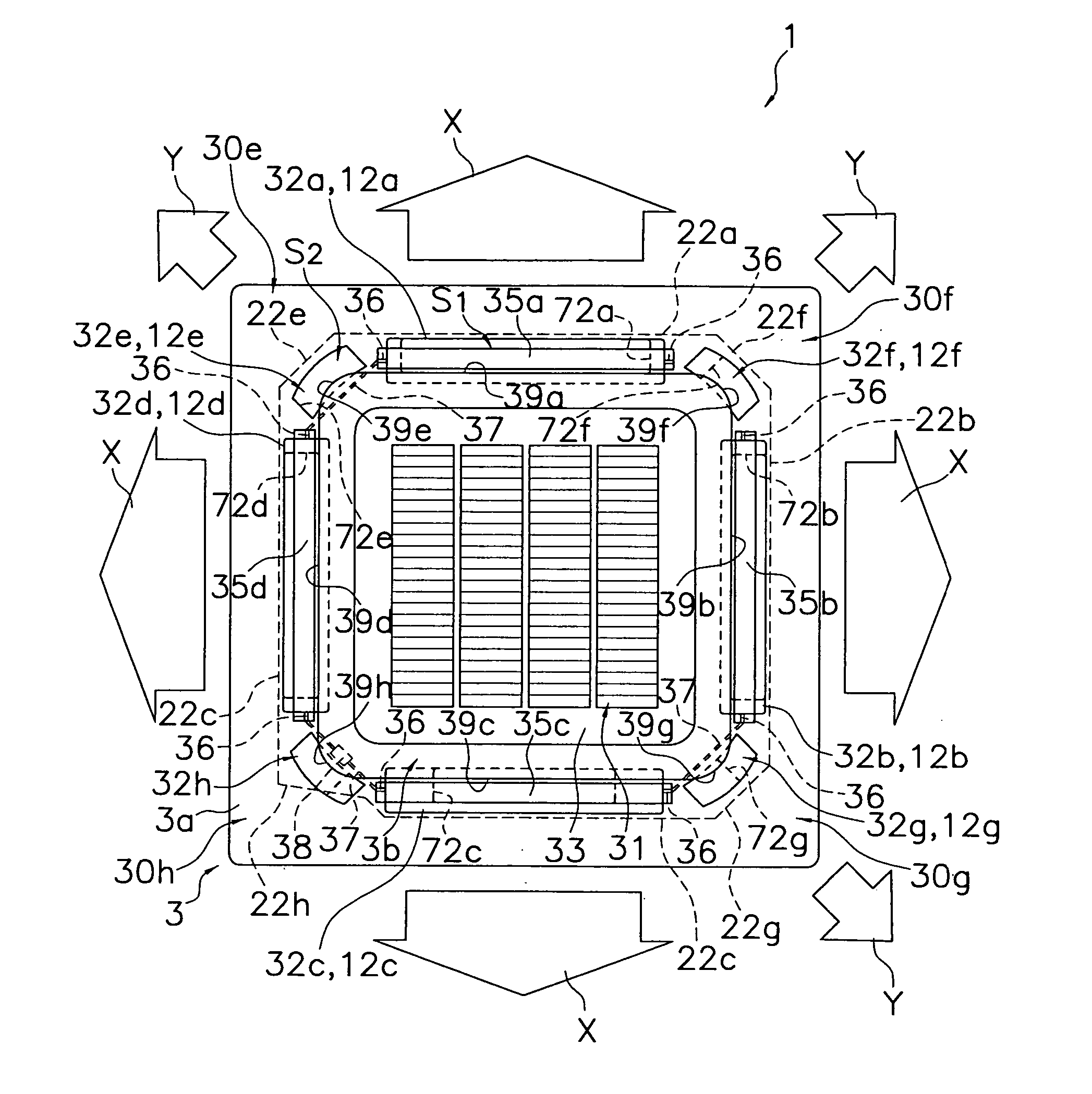
[0009] It is an object of the present invention, in an air conditioner provided in the ceiling of an air conditioned room, to make the air current distribution inside the air conditioned room satisfactory, and to simplify the structure needed to regulate the wind direction of the air current blown out from each of the outlets
[0012] Thus, with this air conditioner, the flow volume of the air is increased by the provision of the auxiliary outlets, the air current distribution inside the air conditioned room can be made satisfactory, and the constitution for regulating the blow-out direction can be simplified.
[0014] With this air conditioner, because the flow speed of the air blown out from each of the main outlets does not decrease significantly, the air current distribution inside the air conditioned room can be made satisfactory by the provision of the auxiliary outlets, and the air blown out from each of the main outlets can reach as far as possible.
[0016] With this air conditioner, the air blown out from each of the auxiliary outlets is blown out in a direction close to the blow-out direction of the air current blown out from each of the main outlets, which makes it easily affected by the air current blown out from each of the main outlets; consequently, it is dragged by the air current blown out from each of the main outlets, tracking characteristics are improved when varying the wind direction of the air current blown out from each of the auxiliary outlets, and the air current distribution inside the air conditioned room can be further satisfactorily maintained.
[0020] With this air conditioner, each horizontal flap can be linked to a link mechanism at a position on the inner side in the longitudinal direction of the end part thereof in the longitudinal direction; consequently, the link mechanism can be disposed further on the inlet side of the auxiliary outlet, and the auxiliary outlets can therefore be formed easily at the corner parts.

Problems solved by technology

However, if the flow volume of the air blown out from each of the outlets is increased, then the flow speed of the air blown out from each of the outlets increases, which unfortunately generates a draft, making it impossible to achieve a satisfactory air current distribution inside the air conditioned room.
Thus, with such an air conditioner, the blowing of the air out from the arcuate outlet increases the flow volume of the air and enables the satisfactory air current distribution inside the air conditioned room; however, it requires the provision of the slide mechanism, which consequently complicates the constitution in order to vary the wind direction of the air current blown out from the outlet, and increases the cost.

Method used


Image

  • Air conditioner
  • Air conditioner
  • Air conditioner

Examples


Embodiment Construction

[0043] The following explains the embodiments of an air conditioner according to the present invention, referencing the drawings.

(1) Basic Constitution of the Air Conditioner

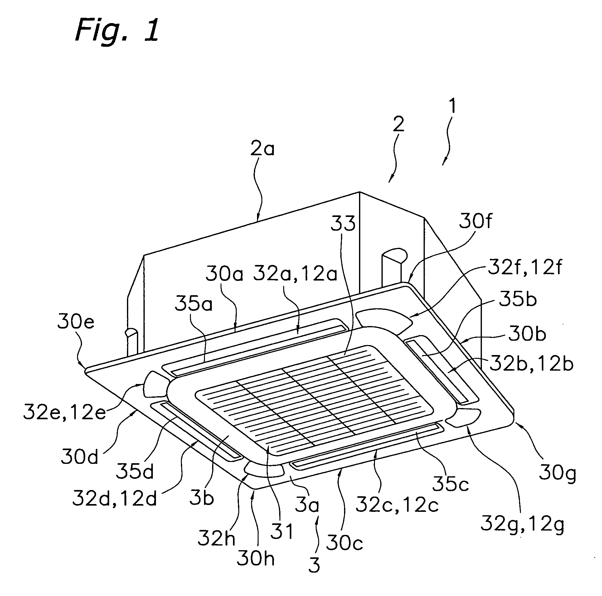
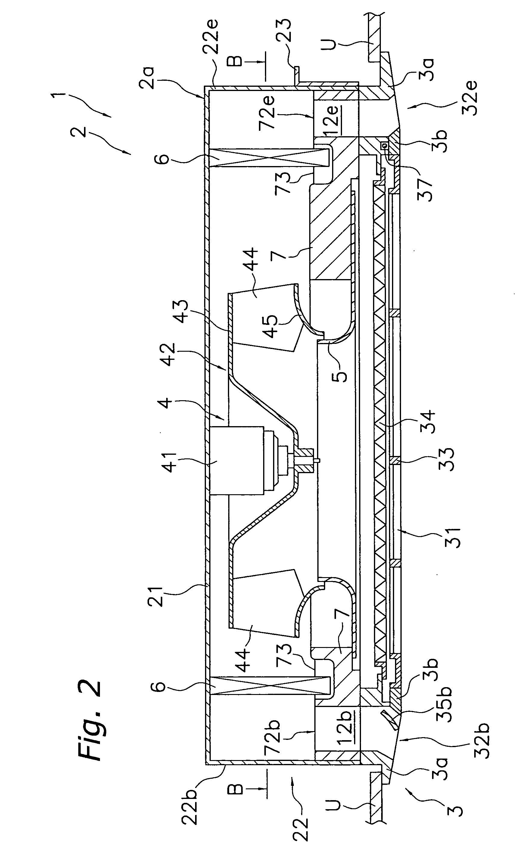
[0044]FIG. 1 is an external perspective view of an air conditioner 1 according to one embodiment of the present invention (ceiling is not shown). The air conditioner 1 is a ceiling embedded type air conditioner, and comprises a casing 2 that internally houses various constituent equipment. The casing 2 comprises a casing main body 2a, and a face panel 3 disposed on the lower side of the casing main body 2a. As shown in FIG. 2, the casing main body 2a is disposed inserted into an opening formed in a ceiling U of the air conditioned room. Furthermore, the face panel 3 is disposed so that it is fitted into the opening of the ceiling U. Here, FIG. 2 is a schematic side cross sectional view of the air conditioner 1, and is a cross sectional view taken along the A-O-A line in FIG. 3.

[0045] As shown in FIG. 2 and F...


PUM


Abstract

An air conditioner principally includes a casing having a casing lower part formed by an alternating sequence of four panel side parts and four corner parts. The casing further has main outlets disposed along each of the panel side parts, and auxiliary outlets disposed at the corner parts. The air conditioner further includes horizontal flaps rotatable supported about longitudinal axes of the main outlets. A circumferential edge part of each of the auxiliary outlets is formed so that the air from each of the auxiliary outlets is blown out in a fixed direction.

Description

FIELD OF THE INVENTION [0001] The present invention relates to an air conditioner, and more particularly relates to an air conditioner provided in the ceiling of an air conditioned room. RELATED ART [0002] A conventional air conditioner provided in the ceiling of an air conditioned room principally comprises: a casing having a casing lower part formed by an alternating sequence of four side parts and four corner parts; outlets disposed so that each runs along a side part and an inlet disposed so that it is surrounded by all the side parts; a fan and a heat exchanger disposed inside the casing; and horizontal flaps each oscillatably provided around the axis of each outlet in the longitudinal direction and capable of varying the wind direction of the air current blown out from each outlet. A motor, link mechanisms, and the like, for oscillating these horizontal flaps, are disposed at the corner parts of a face panel that constitutes the casing lower part in, for example, a ceiling emb...

Claims


Application Information

Patent Timeline
Patent Type & Authority Applications(United States)
IPC IPC(8): F25D23/12F25D17/04F25D17/06F24F13/14F24F13/15F24F13/20F24F13/32
CPCF24F1/0011F24F13/1413F24F13/20F24F13/222F24F2001/0037F24F2013/0616F24F1/0014F24F1/0047
Inventor SAKASHITA, AKIHIKOSANAGI, TSUNEHISATERAKAWA, AZUMI
Owner DAIKIN IND LTD
Learn More