
Pump body components and fluid machinery

A technology of components and pump bodies, applied in the field of rotary cylinder compressors, can solve problems such as obstruction of oil flow paths

Active Publication Date: 2022-02-11
GREE ELECTRIC APPLIANCES INC
View PDF4 Cites 0 Cited by
  • Summary
  • Abstract
  • Description
  • Claims
  • Application Information

AI Technical Summary

Problems solved by technology

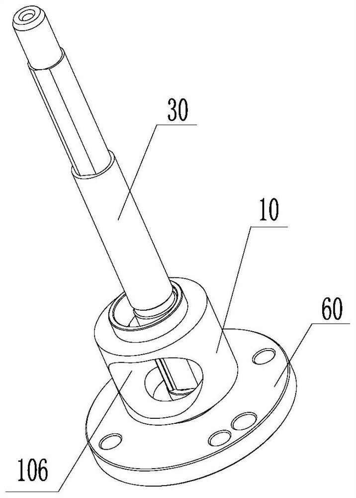
[0005] The main purpose of the present invention is to provide a pump body assembly and a fluid machine to solve the problem that the flange structure obstructs the oil flow path in the prior art

Method used


Image

  • Pump body components and fluid machinery
  • Pump body components and fluid machinery
  • Pump body components and fluid machinery

Examples


Embodiment Construction

[0041] It should be noted that, in the case of no conflict, the embodiments in the present application and the features in the embodiments can be combined with each other. The present invention will be described in detail below with reference to the accompanying drawings and examples.

[0042] It should be noted that, unless otherwise specified, all technical and scientific terms used in this application have the same meaning as commonly understood by those of ordinary skill in the art to which this application belongs.

[0043] In the present invention, unless stated otherwise, the used orientation words such as "upper, lower, top, bottom" are usually for the directions shown in the drawings, or for the parts themselves in the vertical, In terms of vertical or gravitational direction; similarly, for the convenience of understanding and description, "inner and outer" refer to the inner and outer relative to the outline of each component itself, but the above orientation words ...


PUM


Abstract

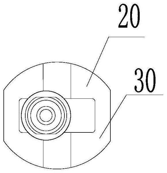
The invention provides a pump body assembly and a fluid machine. The pump body assembly includes a cylinder, which is rotatably arranged; a flange structure, which is located on one side of the cylinder and has a positioning boss extending into the cylinder, and a wall hollow recess is arranged on the positioning boss. The pump body assembly of the present invention solves the problem in the prior art that the flange structure obstructs the oil flow path.

Description

technical field [0001] The invention relates to the technical field related to rotary cylinder compressors, in particular to a pump body assembly and a fluid machine. Background technique [0002] Taking the rotary cylinder compressor as an example, the rotary cylinder compressor is a new type of positive displacement compressor. During the operation of the rotary cylinder compressor, the cylinder and the rotating shaft of the pump body assembly of the compressor rotate around their respective centers, and the piston reciprocates simultaneously relative to the cylinder and the rotating shaft. The rotating shaft passes through the inner hole of the piston, and the rotating shaft divides the inner hole of the piston into two cavities. The reciprocating movement of the piston relative to the rotating shaft realizes the periodic enlargement and shrinkage of the cavity, and the oil in the cavity is squeezed. The bottom continuously flows back and forth between the two cavities. ...

Claims


Application Information

Patent Timeline
Patent Type & Authority Patents(China)
IPC IPC(8): F04B39/00F04B39/12
CPCF04B39/0005F04B39/122F04B39/126
Inventor 杜忠诚任丽萍宋雪威张荣婷李直张培林
Owner GREE ELECTRIC APPLIANCES INC
Learn More