
Dual-axis chain support assembly

a technology of supporting assembly and chain, which is applied in the direction of anchoring arrangements, vessel construction, anchoring chains, etc., can solve the problems of complex design, inability to reduce the bending moments of the anchor chain in a direction parallel to the axis, and fatigue, and achieve the effect of reducing or eliminating the bending moments

Active Publication Date: 2006-09-28
SOFEC
View PDF12 Cites 37 Cited by
  • Summary
  • Abstract
  • Description
  • Claims
  • Application Information

AI Technical Summary

Benefits of technology

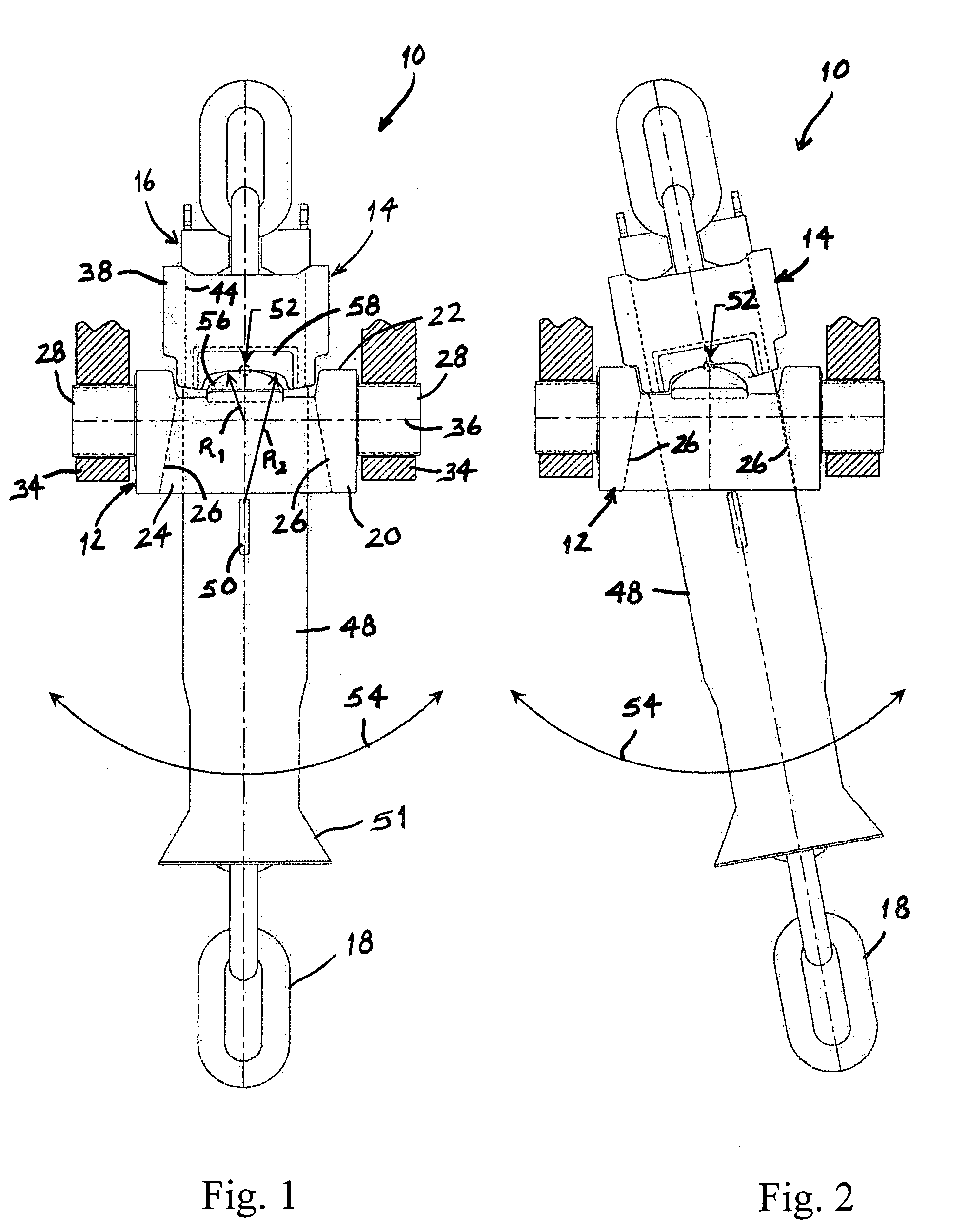
[0011] Thus, the support assembly of the present invention provides a relatively simple mechanism for releasably securing a mooring line, such as an anchor chain, to a floating vessel. In addition, the support assembly is pivotable about two axis, and when these axes are oriented generally perpendicular to each other, the support assembly is able to pivot in virtually any direction in the plane which is parallel to both of these axes. Consequently, the links of the anchor chain which are positioned in the support assembly will remain in alignment, which will reduce or eliminate the bending moments on these links that could otherwise cause them to fatigue and fail.

Problems solved by technology

However, when the vessel pitches and rolls, the anchor chain bends relative to the chain support assembly, and this bending can induce significant bending moments in the anchor chain which can cause it to fatigue and fail.
Although such chain support assemblies reduce the bending moments on the anchor chain in a direction perpendicular to this axis, they are not capable of reducing the bending moments on the anchor chain in a direction parallel to the axis.
However, while these chain support assemblies are capable of significantly reducing the bending moments on the anchor chain, they are often complicated in design and, therefore, difficult and expensive to construct.

Method used


Image

  • Dual-axis chain support assembly
  • Dual-axis chain support assembly
  • Dual-axis chain support assembly

Examples


Embodiment Construction

[0026] The support assembly of the present invention is designed to facilitate the connection of a mooring line to a floating vessel, such as a loading buoy or an FPSO. In addition, the support assembly can be used with any of a variety of mooring lines, including anchor chains and cables. For purposes of simplicity, however, the present invention will be described below in the context of a chain support assembly which is used to facilitate the connection of an anchor chain to the floating vessel.

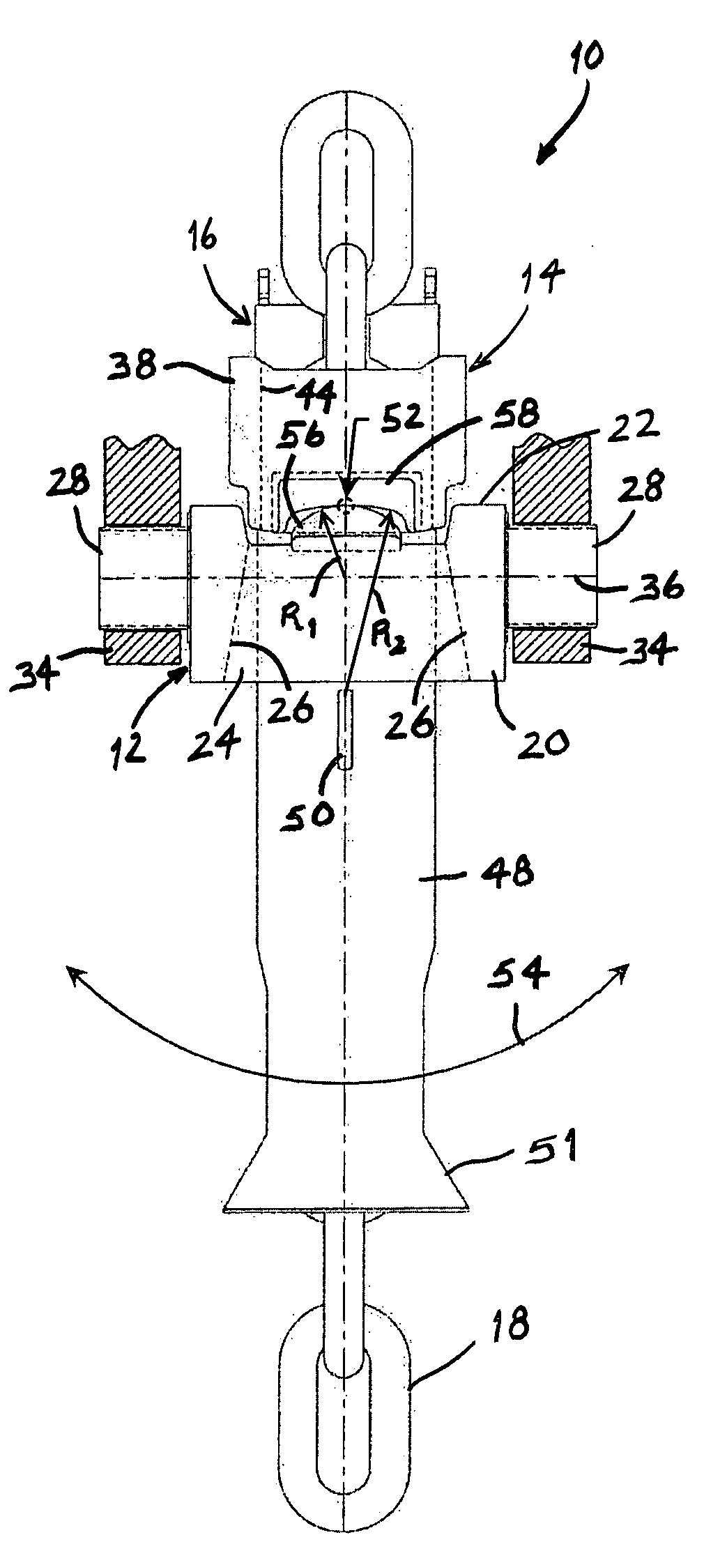
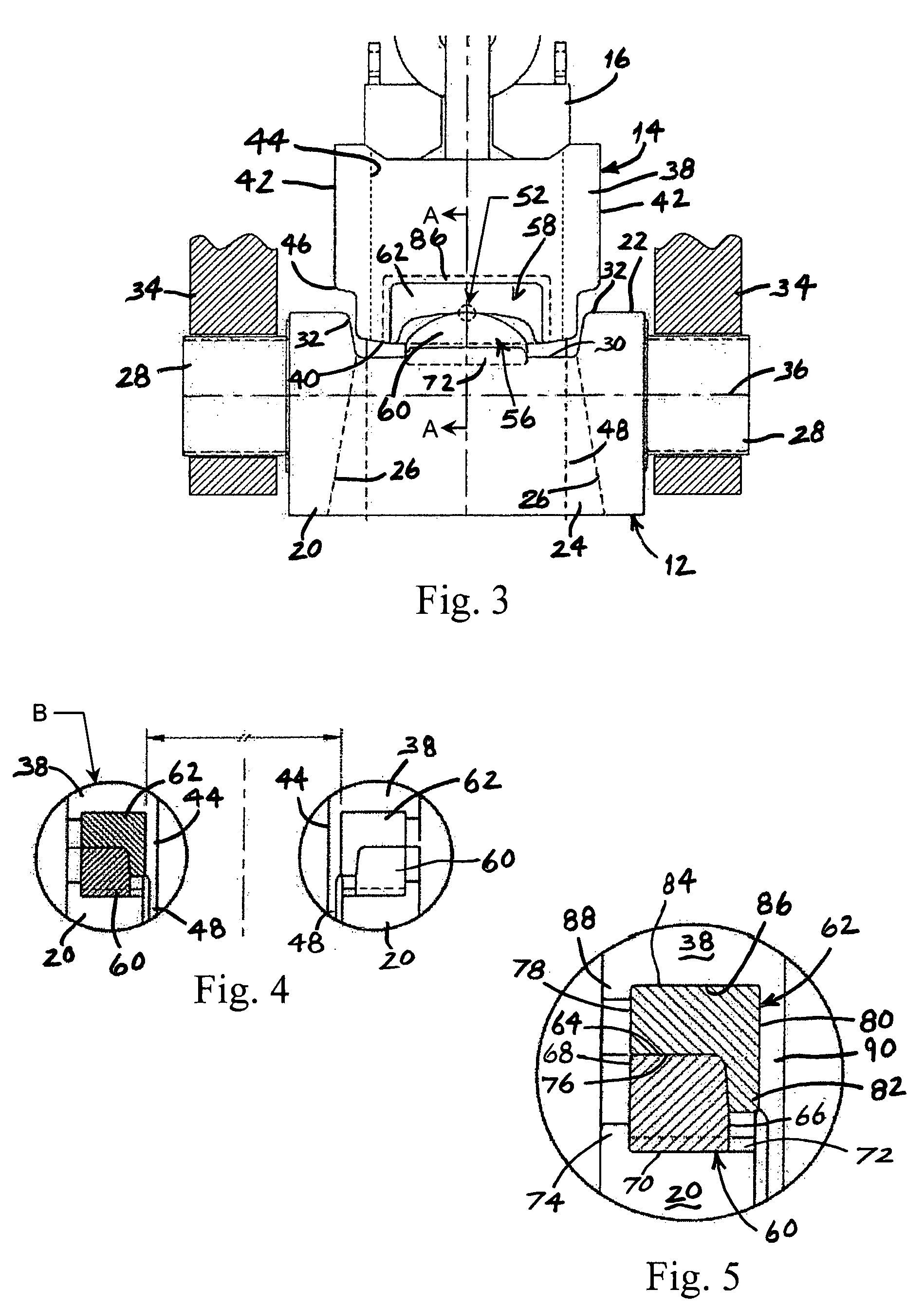
[0027] Referring to FIGS. 1 and 2, the chain stopper assembly of the present invention, which is indicated generally by reference number 10, is shown to comprise a trunnion block 12 which is pivotally supported on the vessel (not shown), and a stopper block 14 which is pivotally supported on the trunnion block. The stopper block 14 may include a conventional chain stopper 16, such as a ratcheting-type chain stopper, which releasably engages an anchor chain 18 to thereby secure the anchor c...


PUM


Abstract

A support assembly for a mooring line of a floating vessel comprises a trunnion block which is pivotally supported on the vessel and a stopper block to which the mooring line is releasably secured. One of the trunnion block and the stopper block comprises a convex surface and the other of the trunnion block and the stopper block comprises a concave surface. In operation, the convex surface engages the concave surface to thereby pivotally support the stopper block on the trunnion block.

Description

BACKGROUND OF THE INVENTION [0001] The present invention relates to a support assembly for connecting one or more mooring lines to a floating vessel, such as a loading buoy or a floating production storage and offloading (“FPSO”) vessel. In particular, the invention relates to a support assembly which is pivotable about two generally perpendicular axes to thereby minimize bending fatigue on the mooring lines. [0002] Mooring line support assemblies are commonly employed to releasably secure a mooring line to a floating vessel. For example, a chain support assembly is used to releasably secure an anchor chain to a vessel. However, when the vessel pitches and rolls, the anchor chain bends relative to the chain support assembly, and this bending can induce significant bending moments in the anchor chain which can cause it to fatigue and fail. [0003] Therefore, prior art chain support assemblies often include means to pivotally connect the chain support assembly to the vessel so that the...

Claims


Application Information

Patent Timeline
IPC IPC(8): B63B21/00
CPCB63B21/18B63B21/10
Inventor BOATMAN, L. TERRYFONTENOT, WILLIAM L.MICKAN, ROGER D.
Owner SOFEC
Learn More