This helps you quickly interpret patents by identifying the three key elements:
Problems solved by technology
Method used
Benefits of technology
[0016] The present invention relates to a leash assembly designed to allow control of a dog or other animal by a handler and which is structured to accomplish a quick detachment of the animal from a remote position without requiring the direct handling or manipulation of the quick connect coupling assembly serving to interconnect the collar, harness, or similar attachment assembly to the distal end of the lead. The present invention is also designed and structured to provide a quick and efficient attachment of a lead to an attachment assembly utilizing only a sin
Problems solved by technology
Attachment of the animal can be extremely difficult, particularly when the dog or animal being tethered is overly frisky or otherwise in an excited state.
Also, in accomplishing either attachment or detachment of the lead from the collar or like harness particular problems are encountered by the elderly or by those who are visually or otherwise physically challenged.
However, in cases of emergency, it is equally important that the animal be released or detached from his controlling lead as quickly as possible as it could be dangerous for the animal to begin running while dragging the lead or any part of the leash assembly.
Conversely, if the animal is loose, it may be necessary to quickly re-harness the animal in order to restrain its movement in a hazardous situation.
A further problem is encountered in the handling, and in particular, the transportation, of horses.
Specifically, when a horse is being confined in a trailer they often become anxious and/or excited.
Combined with the tight space limitations of most trailers, the excited condition of the animal presents a dangerous situation for the handler who must enter the trailer to either attach or release the animal from the trailer.
In particular, although the prior art devices allow the length of the lead, and thus, the distance between the animal and the handler, or a fixed
Method used
Image
Click on the blue label to locate the original text in one second.
Reading with bidirectional positioning of images and text.
Examples
Embodiment Construction
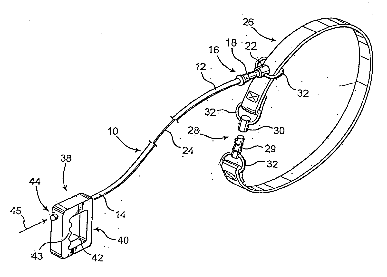
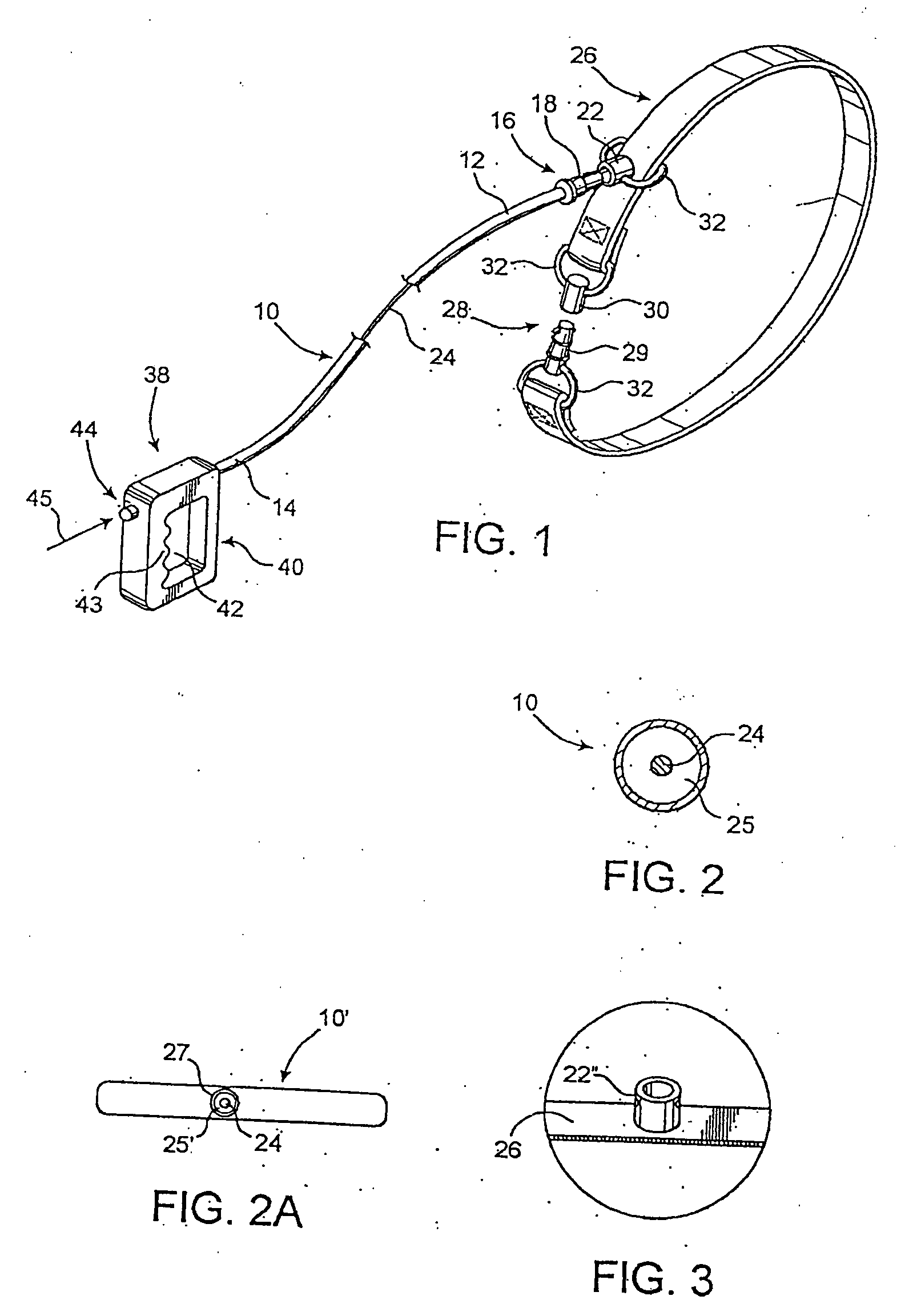
[0080] As shown in the accompanying Figures, the present invention is directed towards a retractable leash assembly wherein a preferred embodiment is disclosed in FIG. 1 and includes a lead as in 10 being of any applicable or desired length and further being formed of a flexible material so as to facilitate freedom of movement of both the animal and the handler or user of the subject assembly, and to a quick connect coupling assembly which includes a coupling assembly generally shown as 16, a release structure generally shown as 24, and an activation assembly generally shown as 38, as disclosed herein.
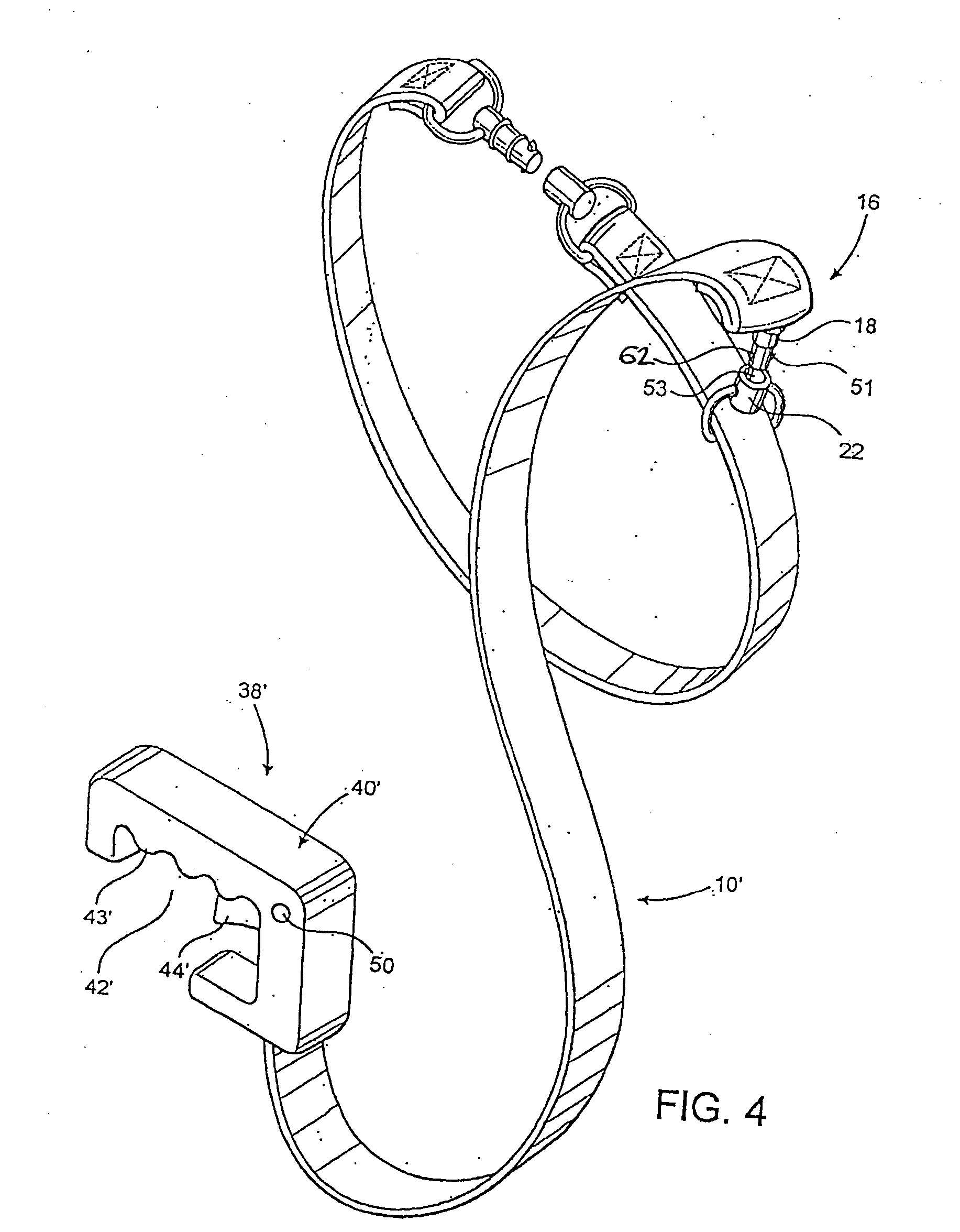
[0081] The lead 10 terminates at a distal end 12 and a proximal end 14, which are oppositely disposed relative to one another. Moreover, a coupling assembly 16 is secured, at least in part, adjacent the distal end 12 of the lead 10 and includes a first component as in 18 and a second component as in 22. The first component 18 may be secured to the distal end 12 of the lead 10 and is c...
PUM
Abstract
A quick connect coupling assembly has a first and second component, and a locking assembly structured to retain the components in an attached orientation with one another. The locking assembly includes a plurality of locking elements each having a locking arm with a locking member mounted to a distal end, wherein the locking members are maintained in an outwardly extending orientation by a biasing mechanism. The biasing mechanism may comprise magnetic biasing elements attached to each oppositely disposed locking element, the magnetic biasing elements structured to create a repulsive magnetic force between one another. The quick connect coupling assembly also includes a release mechanism to permit the locking members to be temporarily disposed into a retracted orientation, thereby permitting the first and second components to be detached from one another.
Description
CLAIM OF PRIORITY [0001] This is a continuation-in-part application of presently pending U.S. patent application Ser. No. 10 / 787,338 filed on Feb. 26, 2004, which is a continuation-in-part of U.S. patent application Ser. No. 10 / 371,028 filed on Feb. 20, 2003, now U.S. Pat. No. 6,955,138, which is a continuation-in-part of U.S. patent application Ser. No. 09 / 867,338 filed on May 29, 2001, now U.S. Pat. No. 6,629,511, which is a continuation-in-part of U.S. patent application Ser. No. 09 / 195,965 filed on Nov. 19, 1998, now U.S. Pat. No. 6,247,427, which is a continuation-in-part of U.S. patent application Ser. No. 08 / 958,111 filed on Oct. 27, 1997, now abandoned, which claims priority under 35 U.S.C. 119(e) to provisional patent application having Ser. No. 60 / 029,573 having a filing date of Oct. 28, 1996, each of which are incorporated by reference in their entirety herein.BACKGROUND OF THE INVENTION [0002] 1. Field of the Invention [0003] The present invention is directed to a quick ...
Claims
Application Information
Patent Timeline
Application Date:The date an application was filed.
Publication Date:The date a patent or application was officially published.
First Publication Date:The earliest publication date of a patent with the same application number.
Issue Date:Publication date of the patent grant document.
PCT Entry Date:The Entry date of PCT National Phase.
Estimated Expiry Date:The statutory expiry date of a patent right according to the Patent Law, and it is the longest term of protection that the patent right can achieve without the termination of the patent right due to other reasons(Term extension factor has been taken into account ).
Invalid Date:Actual expiry date is based on effective date or publication date of legal transaction data of invalid patent.