
Molded member with foamed body

a technology of foamed body and molded parts, which is applied in the directions of pedestrian/occupant safety arrangements, vehicular safety arrangements, other domestic objects, etc., can solve the problems of increased manufacturing cost, deformation and thermal deformation of molding deformation of first member and second member, and deformation of instrument panel textur

Active Publication Date: 2006-09-28
INOAC CORP
View PDF4 Cites 41 Cited by
  • Summary
  • Abstract
  • Description
  • Claims
  • Application Information

AI Technical Summary

Benefits of technology

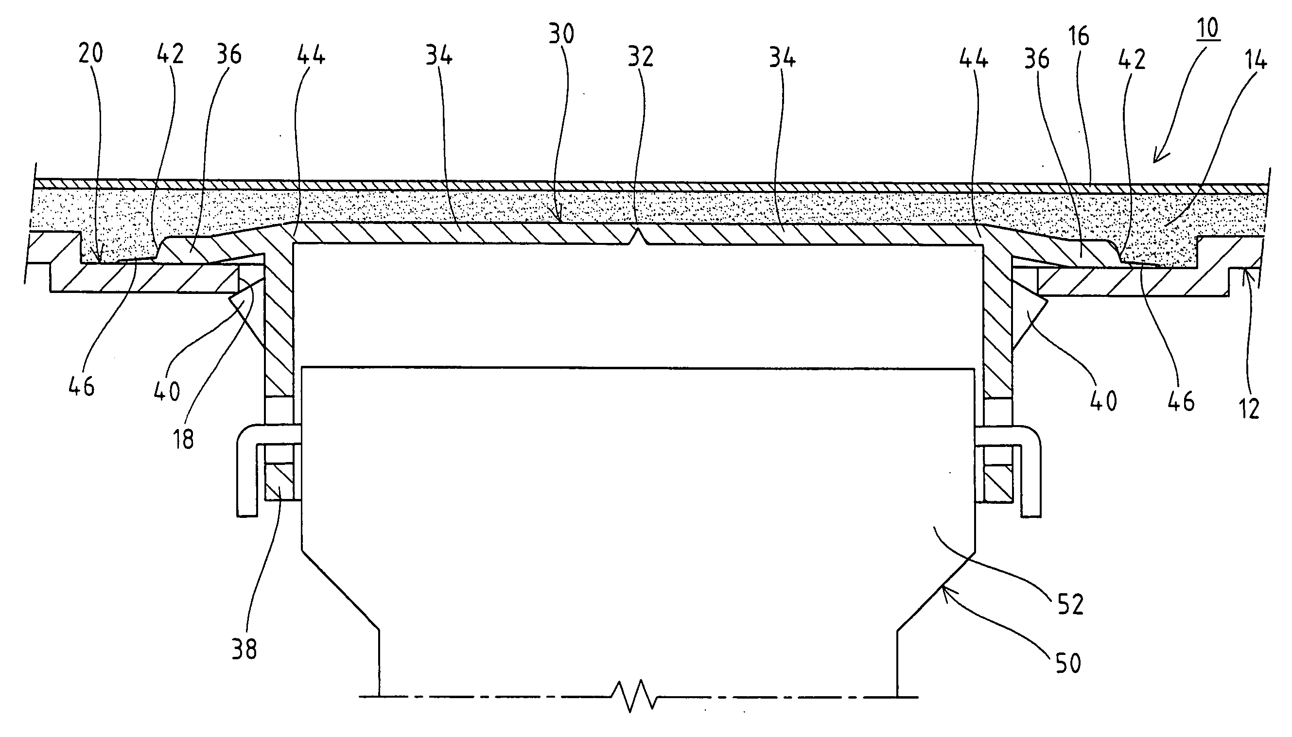
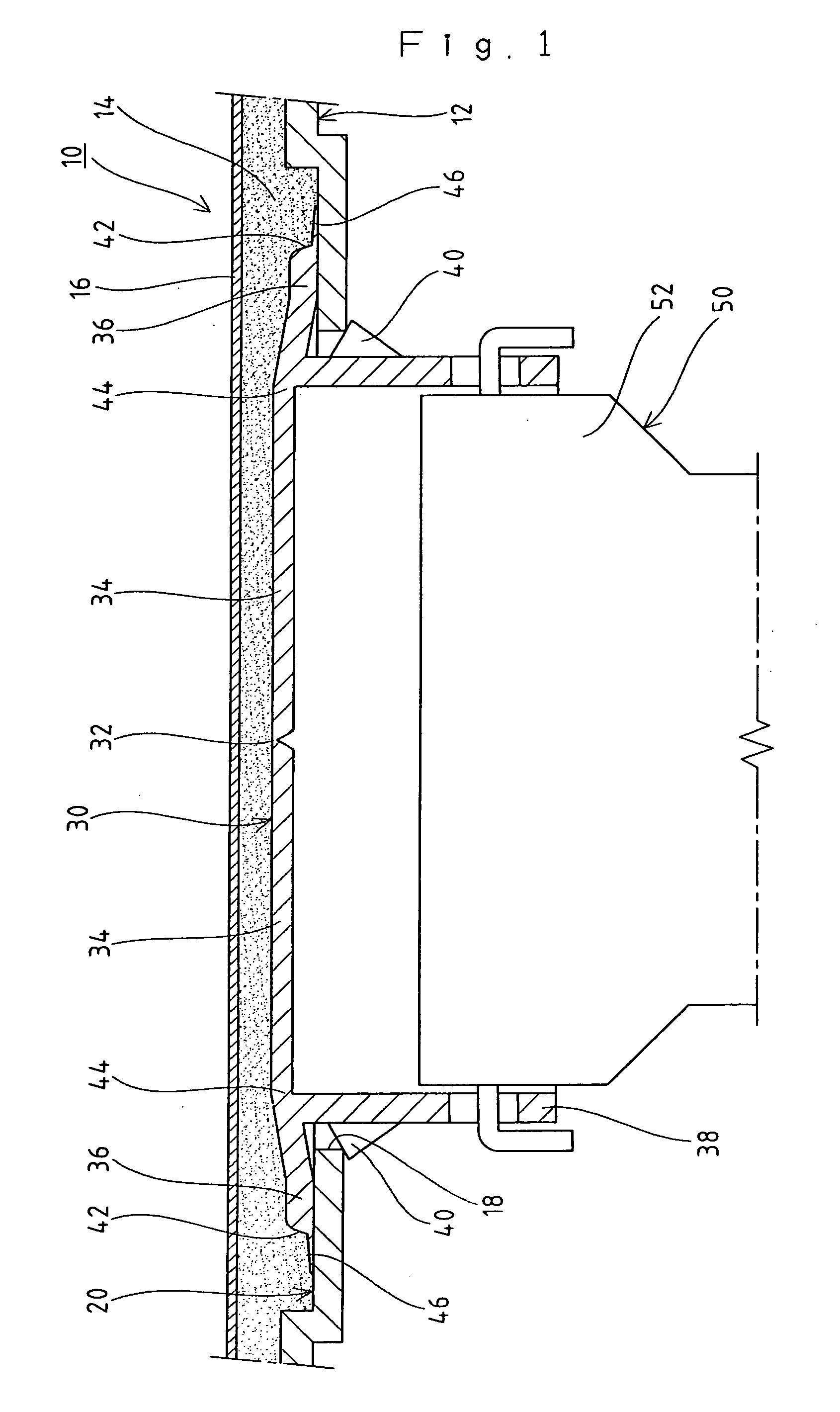
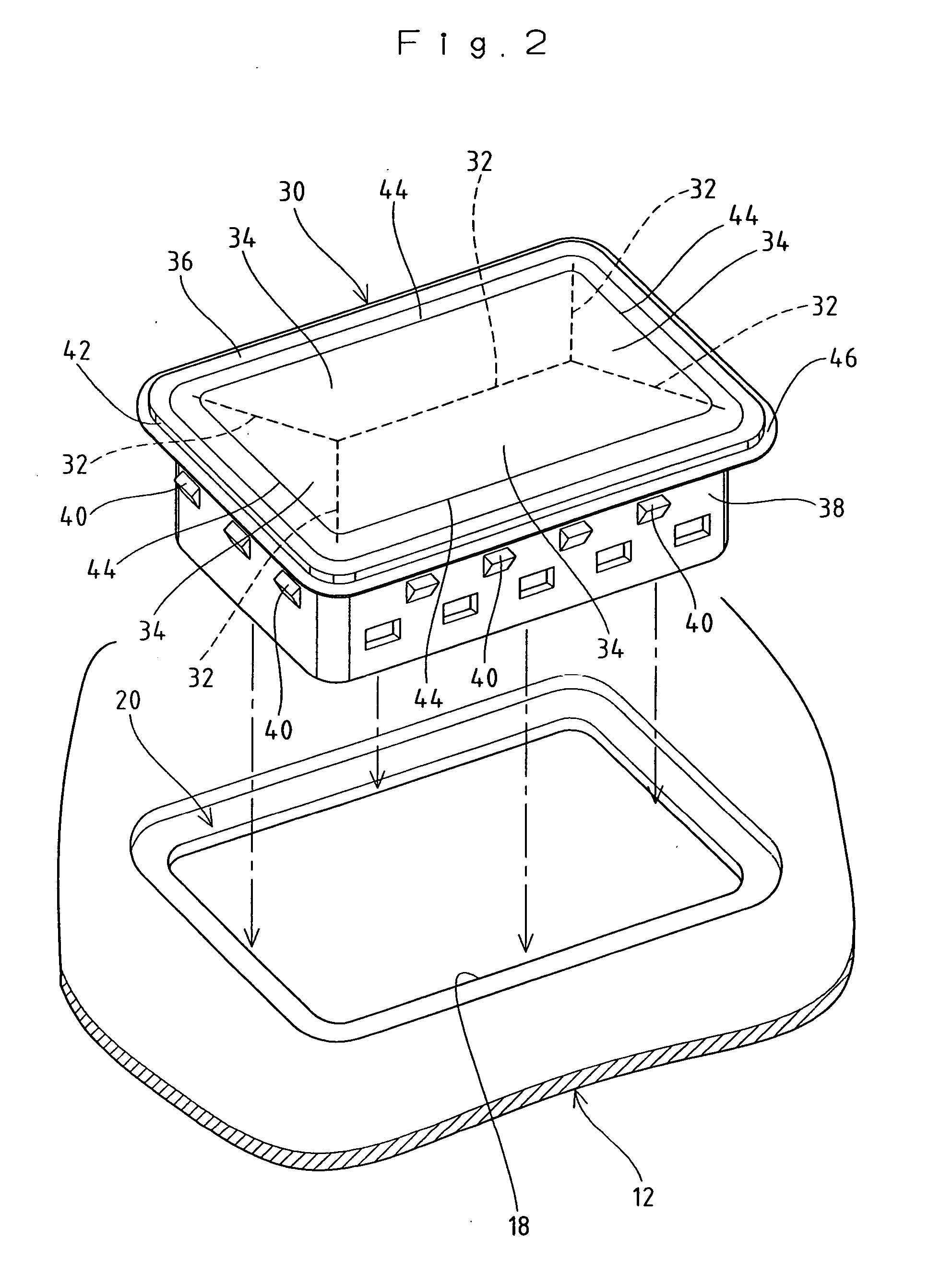
The invention provides a molded member with a foamed body that prevents leakage of the foam by sealing the first and second members. A seal piece is provided at the outer edge of the second member to prevent the foam from leaking from the clearance between the abutment surfaces of the first and second members. This results in a better seal and prevents the foam from leaking during use.

Problems solved by technology

Being a molded member of a synthetic resin, both the base material (first member) and the airbag door (second member) are likely to suffer molding deformation and thermal deformation.
When the foamed body is foamed on the top surface sides of the base material and the airbag door, therefore, a part of the foamed body whose foaming reaction is in progress enters the clearance produced between the abutment surfaces of both members and leaks to the back side of the base material through the opening.
This undesirably degrades the texture of the instrument panel.
This method however brings about an additional problem of an increased manufacture cost due to, for example, (a) the cost of the material for the seal member and (b) increases in the number of work steps and work time for laying the seal member.
After completion of injection molding, therefore, the step of cutting off the burr (process prior to molding of the foamed body) is needed, which leads to an increase in manufacture cost.

Method used


Image

  • Molded member with foamed body
  • Molded member with foamed body
  • Molded member with foamed body

Examples


Embodiment Construction

[0024] A preferred embodiment of a molded member with a foamed body according to the invention will now be described referring to the accompanying drawings.

[0025] As mentioned earlier, the “molded member with a foamed body” as defined in the present application is premised on that the molded member has a member molded into a required shape and a foamed body foamed on the top surface side of the member and provided in close contact with the member and comprises a first member with an opening of a required shape and a second member provided on the top surface side of the first member to completely cover the opening. Because one example of such a molded member with a foamed body is an instrument panel as exemplified in, for example, FIGS. 8 and 9, the following description of the embodiment will be given referring to the instrument panel. Accordingly, those members and portions which are identical to those of the prior art explained already are denoted by the same reference numerals. ...


PUM

PropertyMeasurementUnit
distanceaaaaaaaaaa
thicknessaaaaaaaaaa
widthaaaaaaaaaa

Abstract

Disclosed is a molded member with a foamed body, which is foamed on the top surface sides of a first member and a second member and is prevented from leaking from between abutment surfaces of those members toward the back side. A seal piece of a required width extending in an eaves form outward over the perimeter of the outer contour edge of an airbag door is provided at the outer contour edge. When the airbag door is laid out at a door mount portion, so formed as to surround an opening formed in a base material, the seal piece is set in close contact with the outer surface of the door mount portion in such a way as to surround the opening. This prevents the foamed body, foamed on the top surface side of the base material facing the airbag door, from leaking from a clearance, produced between abutment surface of the base material and the airbag door, toward the back side.

Description

FIELD OF THE INVENTION [0001] The present invention relates to a molded member with a foamed body, and, more particularly, to a molded member comprising a first member having an opening of a required shape formed therein, a second member provided on the top surface side of the first member to completely cover the opening, and a foamed body foamed between the top surface sides of the first and second members and provided in close contact with both members. DESCRIPTION OF THE RELATED ART [0002] One example of a so-called “molded member with a foamed body”, which has a member molded into a required shape and a foamed body foamed on the top surface side of the member and provided in close contact with the member is an instrument panel as an upholstered member of a vehicle as exemplified in FIGS. 8 and 9. The illustrated instrument panel has a 3-layer structure where a skin is laid out on the outer surface of a foamed body, provided in close contact with a base material as a member, in s...

Claims


Application Information

Patent Timeline
Patent Type & Authority Applications(United States)
IPC IPC(8): B60R21/20B60R21/16
CPCB29C44/1228B29C44/351B29L2022/027B29L2031/3038B60R21/205B60R21/2165B29C44/14
Inventor OKAMOTO, SHINJISUZUKICHIBA, TOMOHIRO
Owner INOAC CORP
Learn More