Stolen vehicle recovery support apparatus

a technology for supporting apparatus and stolen vehicles, applied in the direction of cycle equipment, anti-theft cycle equipment, anti-theft device, etc., can solve problems such as adverse effects

Inactive Publication Date: 2006-09-28
FUJITSU GENERAL LTD +1
View PDF8 Cites 9 Cited by
  • Summary
  • Abstract
  • Description
  • Claims
  • Application Information

AI Technical Summary

Benefits of technology

[0010] It is an object of the present invention to at l

Problems solved by technology

Moreover, a recovering means as disclosed in Japanese Patent Application Laid Ope

Method used


Image

  • Stolen vehicle recovery support apparatus
  • Stolen vehicle recovery support apparatus
  • Stolen vehicle recovery support apparatus

Examples


Embodiment Construction

[0017] Exemplary embodiments of the present invention will be described below with reference to accompanying drawings. The present invention is not limited to these embodiments.

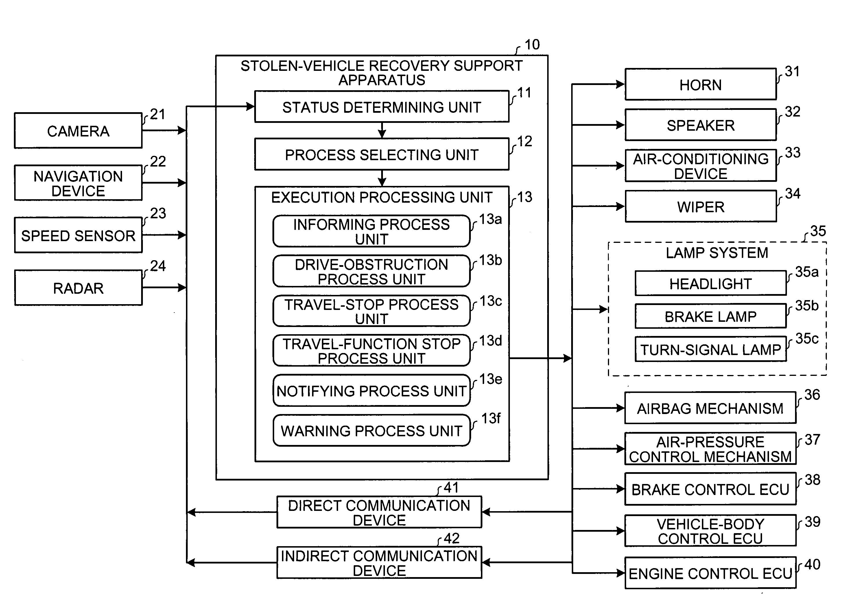
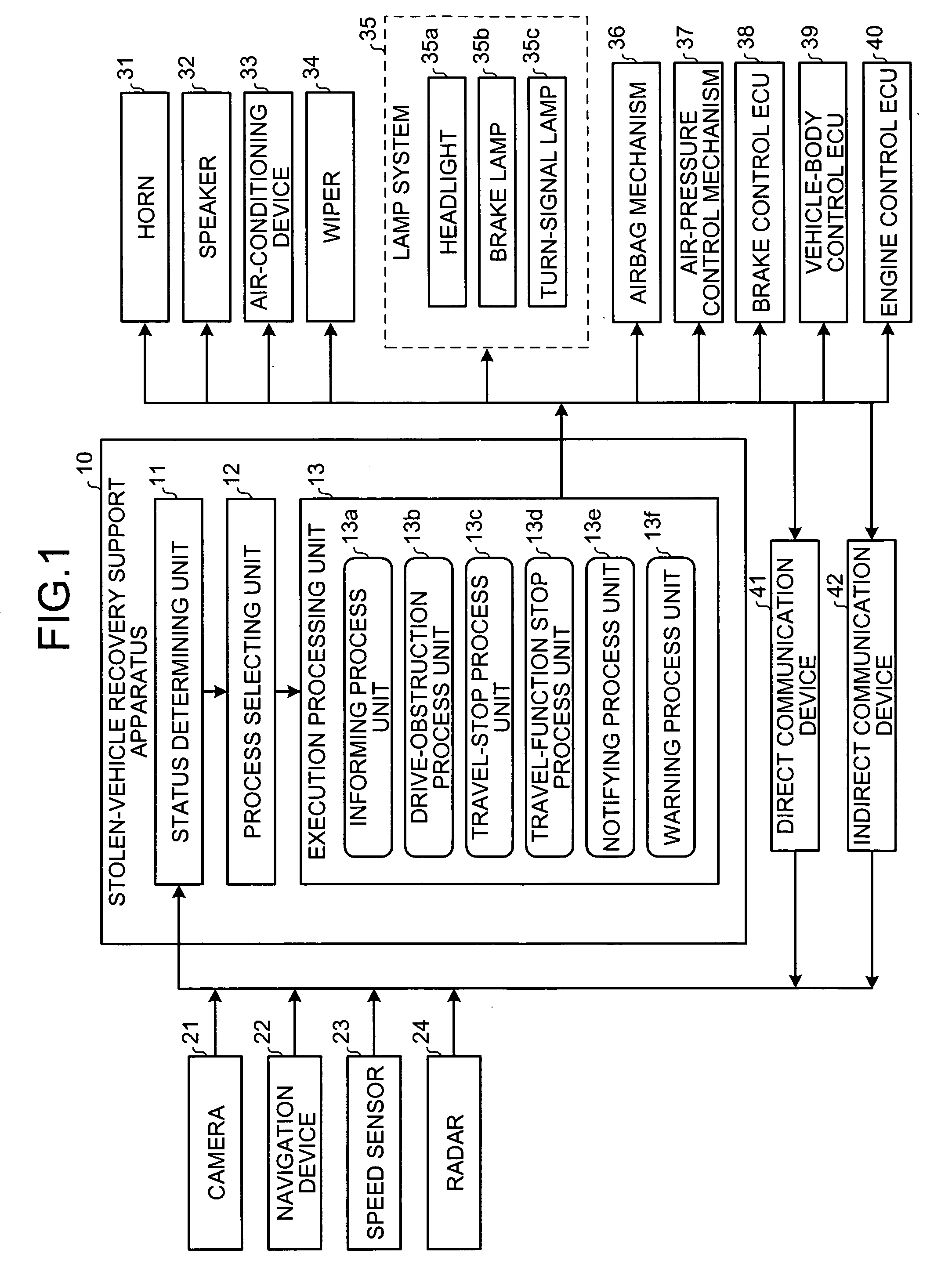
[0018]FIG. 1 is a schematic of a stolen-vehicle recovery support apparatus 10 according to an embodiment of the present invention. The stolen-vehicle recovery support apparatus 10 is connected to a camera 21, a navigation device 22, a speed sensor 23, a radar 24, a horn 31, a speaker 32, an air-conditioning device 33, a wiper 34, a lamp system 35, an airbag mechanism 36, an air-pressure control mechanism 37, a brake control electronic control unit (ECU) 38, a vehicle-body control ECU 39, an engine control ECU 40, a direct communication device 41, and an indirect communication device 42.

[0019] The camera 21 photographs the surroundings and the interior of a vehicle in which the stolen-vehicle recovery support apparatus 10 is provided. The navigation device 22 sets a driving path and guides the vehicle. Speci...


PUM


Abstract

An apparatus for supporting recovery of the vehicle if the vehicle is stolen includes a determining unit that determines whether the vehicle is being stolen. A camera judges a state of the vehicle and an environment around the vehicle. When the determining unit determines that the vehicle is being stolen, a horn of the vehicle is automatically honked.

Description

BACKGROUND OF THE INVENTION [0001] 1. Field of the Invention [0002] The present invention relates to a technology for recovering a stolen vehicle. [0003] 2. Description of the Related Art [0004] There is known a technology for monitoring a vehicle and its surroundings while the driver is away from the vehicle to detect and prevent theft of a vehicle or theft of articles from a vehicle. [0005] Japanese Patent Application Laid Open No. 2002-257013 discloses a technology for preventing auto theft by locking the engine with an immobilizer when theft is detected. Japanese Patent Application Laid Open No. 2003-157483 discloses a technology for photographing the surroundings of a vehicle when an object approaches the vehicle, and transmitting the photographed image when a fraudulent act is committed. [0006] Japanese Patent Application Laid Open No. 2000-142323 discloses a stolen-vehicle prevention device that sets off an alarm when theft is detected based on a change of a connection status...

Claims


Application Information

Patent Timeline
IPC IPC(8): B60R25/10B60R25/00B62H5/00B60R25/01B60R25/02B60R25/04B60R25/08B60R25/102B60R25/104B60R25/30B60R25/31B60R25/32
CPCB60R25/04B60R25/102B60R25/104
Inventor HARUMOTO, SATOSHISAWADA, JUNICHIMAENO, YOSHIHIKONOMORI, HIRONORIMATSUDA, YUUSAKUNAKAMURA, MOTOHIRO
Owner FUJITSU GENERAL LTD
Why Eureka
Try Eureka