Internal digital TV antennas for hand-held telecommunications device

Inactive Publication Date: 2006-09-28
RPX CORP
View PDF5 Cites 99 Cited by
  • Summary
  • Abstract
  • Description
  • Claims
  • Application Information

AI Technical Summary

Benefits of technology

[0006] The first aspect of the present invention provides a method to achieve at least two resonances in an internal antenna structure for receiving digital-video broadcasting signals in a frequency range. The frequency range can be between 470 MHz and 702 MHz, for example. The second aspect of the present invention provides an antenna structure for receiving digital-video broadcasting signals in a frequency range. The antenna structure can be implemented inside a hand-held electronic device and the frequency ra

Problems solved by technology

While it is desirable and advantageous to have an internal compact and unobtrusive DVB-H antenna for mobile terminals, it would be very difficult, if not impossible, to use a simple antenna that is small enough to fit inside current mobile phones even in the frequency range of 470-838 MHz.
Howeve

Method used


Image

  • Internal digital TV antennas for hand-held telecommunications device
  • Internal digital TV antennas for hand-held telecommunications device
  • Internal digital TV antennas for hand-held telecommunications device

Examples


first embodiment

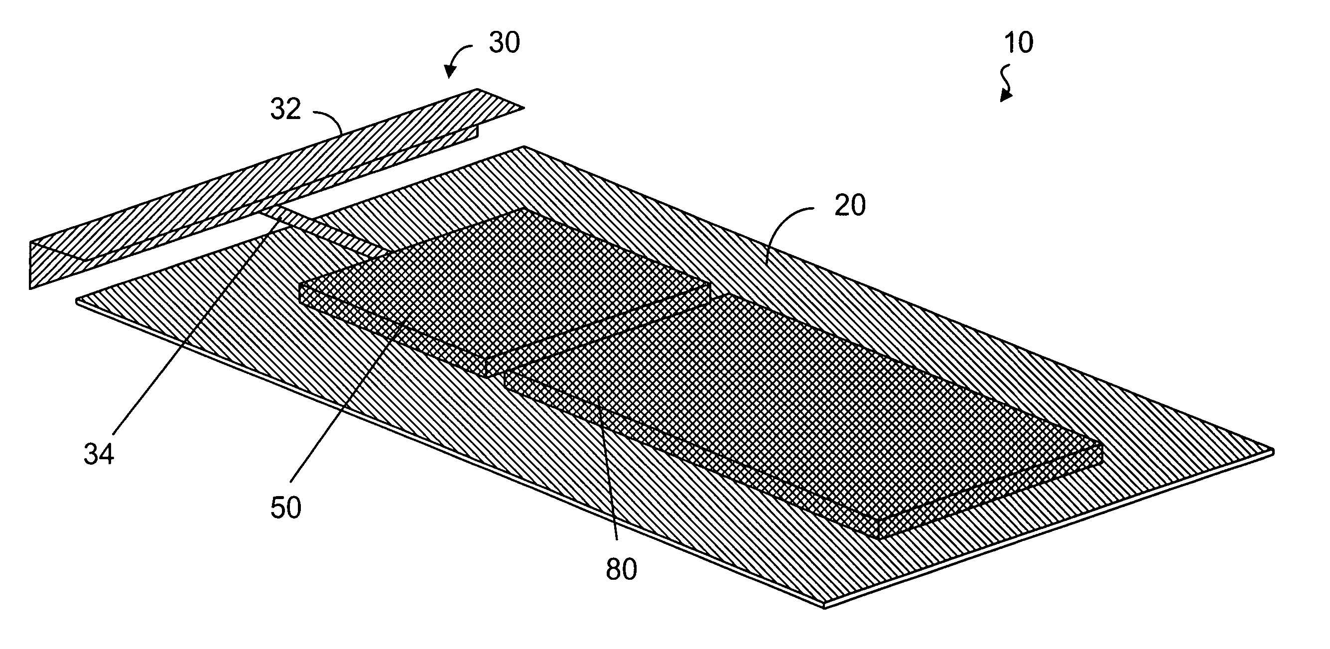
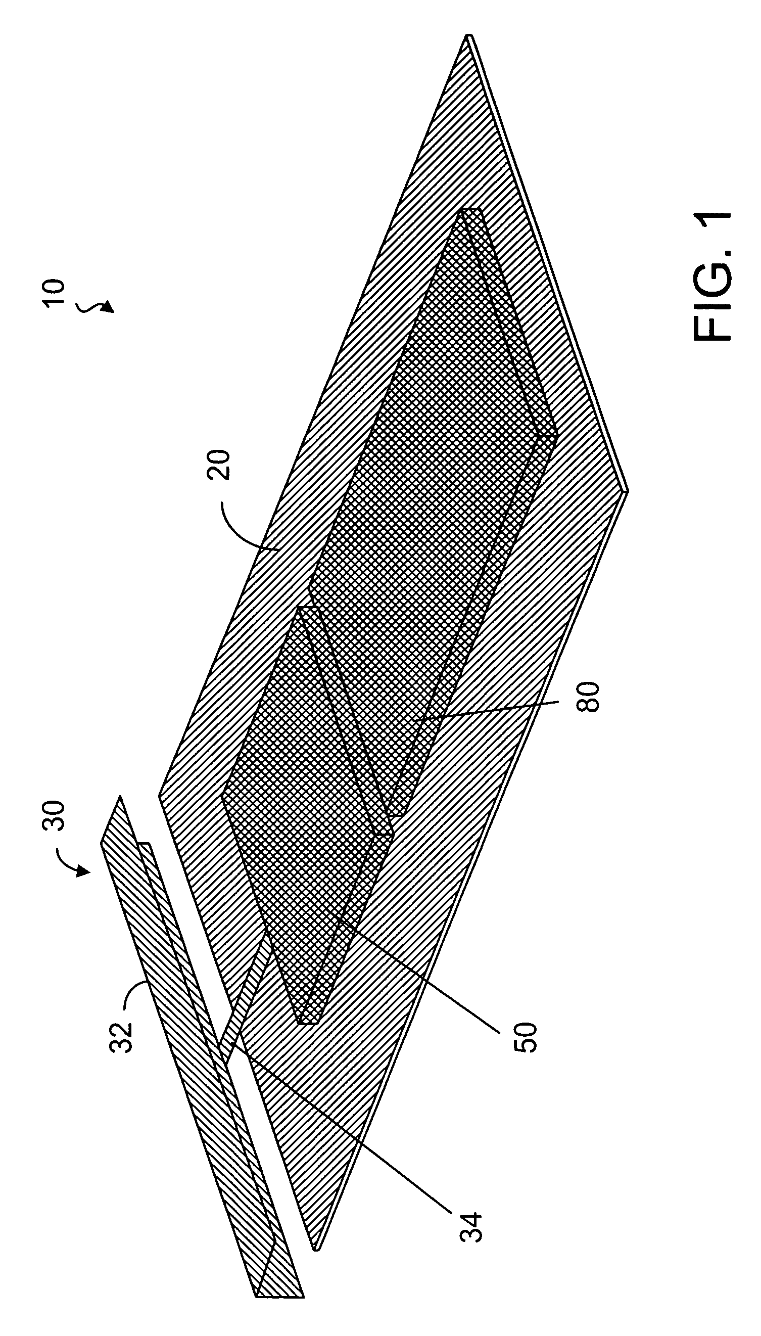
[0035] The first embodiment of the present invention is based on a non-resonant antenna structure. The radiative element of the antenna can be a metal plate folded to have a better fit to the geometry of a mobile terminal, as shown in FIG. 1. FIG. 1 illustrates a circuit board 10 having a printed wire board (PWB) 20 with a ground plane for implementing an unbalanced antenna 30 with a folded radiative element 32 and an antenna feed 34 connected between the radiative element 32 and the PWB 20. The physical and electrical lengths of the radiative element 32 are smaller than λ / 4 at the frequencies of interest (470-702 MHz). The antenna feed 34 is a narrow strip of electrically conductive material connected to a section of the radiative element 32. The antenna is resonated with an external matching circuit, which makes the antenna dual-resonant or multi-resonant and which can be integrated to the antenna module if necessary. As shown in FIG. 1, a matching circuit 50 is connected in serie...

second embodiment

[0038] The second embodiment of the present invention is based on a resonant antenna. The radiative element is an elongated strip of electrically conductive material folded at two sides, as shown in FIG. 5. FIG. 5 illustrates a circuit board 10′ having a PWB 20 with a ground plane for implementing an unbalanced antenna 40 with a folded radiative element 42 and an antenna feed 44 connected between the radiative element 42 and the PWB 20. The physical length of the radiative element is smaller than λ / 4 at the frequencies of interest (470-702 MHz), but the electrical length is about λ / 4. In one embodiment, the electrical length is λ / 4 at 586 MHz (in the middle of the band). The antenna is made dual-resonant or multi-resonant with a matching circuit, which can be integrated to the antenna module, if necessary. For example, it is possible to include the first inductor in the antenna structure as a meandered metal line, as shown in FIG. 5. As shown in FIG. 5, a matching circuit 50 is conn...


PUM


Abstract

An antenna structure comprises an unbalanced antenna for receiving digital video broadcasting signals. The antenna is dimensioned to fit within an electronic device, such as a mobile phone. The unbalanced antenna has a radiative element and a feed line connected to a matching circuit so as to achieve two or more resonances within a DVB-H frequency range, such as 470 to 702 MHz. The physical length of the radiative element is always smaller than λ/4 at the frequencies of interest (470-702 MHz), but the electrical length can be smaller or substantially equal to λ/4. The matching circuit can comprise one or more LC resonators depending on the number of resonances. The resonators can be series or parallel connected between the feed line and RF circuitry for processing the broadcasting signals. The antenna can be tuned to other bands above the DVB-H frequencies for use as a diversity or MIMO antenna.

Description

[0001] This application is based on and claims priority to U.S. provisional patent application Ser. No. 60 / 665,902, filed Mach 24, 2005.FIELD OF THE INVENTION [0002] The present invention generally relates to a radio-frequency antenna and, more specifically, to an internal digital television antenna for use in a hand-held or portable telecommunications device, such as a mobile phone. BACKGROUND OF THE INVENTION [0003] Digital television is coming to hand-held mobile terminals, such as mobile phones. Currently an antenna designed to receive digital video broadcasting is conforming to DVB-H specification, which was developed in 2004 for accessing DVB services on hand-held devices. According to the DVB-H specification, data transmission is carried out in a time-slicing manner such that bursts of data are received at a time. As such, the receiver is allowed to be inactive for much of the time in order to save power. There are two frequency bands designated for DVB services: VHF band of ...

Claims


Application Information

Patent Timeline
IPC IPC(8): H01Q1/24
CPCH01Q1/243H01Q9/30H01Q9/36H01Q21/28
Inventor OLLIKAINEN, JANI
Owner RPX CORP
Why Eureka
Try Eureka