Antenna and wireless IC device

a wireless ic and antenna technology, applied in the structure of resonant antennas, radiating elements, instruments, etc., can solve the problems of reducing the current flowing between the two coils, and reducing the communication distance, so as to increase the impedance to infinity, prevent stray capacitance, and improve the energy transfer efficiency between the antenna and the wireless ic mounted thereon

Active Publication Date: 2011-11-17
MURATA MFG CO LTD
View PDF4 Cites 15 Cited by
  • Summary
  • Abstract
  • Description
  • Claims
  • Application Information

AI Technical Summary

Benefits of technology

[0010]In the antenna and the wireless IC device, the spiral coupling patterns coupled to the antenna pattern preferably are arranged so as to face each other to define a single LC resonator. That is, a capacitor is provided between the spiral coupling patterns arranged so as to face each other, and LC resonance is obtained by using the capacitor and inductances produced by the spiral coupling patterns. This LC resonance increases the impedance to infinity, whereby energy is concentrated in the coupling patterns. As a result, energy transfer efficiency between the antenna and the wireless IC mounted thereon is improved.
[0011]In the antenna and the wireless IC device, the antenna pattern may preferably be a single coil pattern, two coil patterns arranged so as to face each other, or two circular patterns including at least a pair of ends and arranged

Problems solved by technology

Therefore, there is a problem in that the amount of current flowing between the two coils L12 and L13 is decreased and sufficient energy is not tran

Method used


Image

  • Antenna and wireless IC device
  • Antenna and wireless IC device
  • Antenna and wireless IC device

Examples


first preferred embodiment

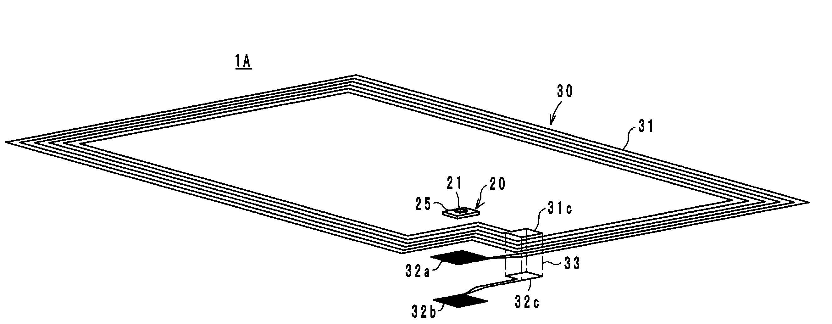
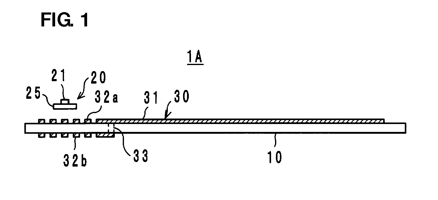
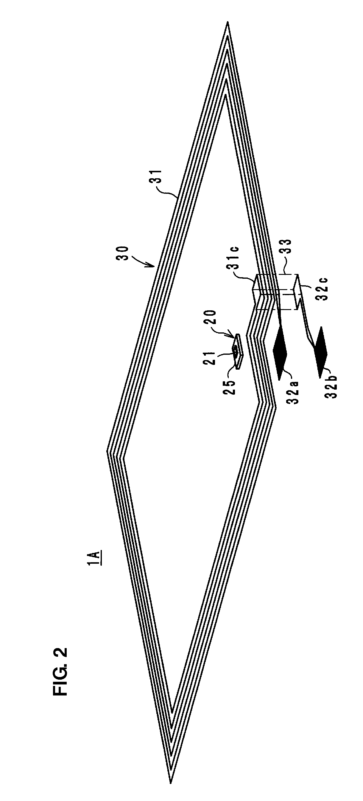
[0029]A wireless IC device 1A according to a first preferred embodiment of the present invention preferably includes a substrate 10, a coupling module 20, and an antenna 30, as shown in FIGS. 1 and 2. The coupling module 20 includes a wireless IC chip 21 and a feeder circuit substrate 25 including a feeder circuit arranged to be coupled to the wireless IC chip 21. The antenna 30 includes a coil pattern 31 and spiral coupling patterns 32a and 32b that are provided at the ends of the coil pattern 31 and arranged so as to face each other.

[0030]The substrate 10 is preferably made of a dielectric, such as a PET film, for example. The coil pattern 31 preferably has a coil shape on the front surface of the substrate 10, as shown in FIG. 2. The spiral coupling pattern 32a is provided at one end thereof. The spiral coupling pattern 32b is arranged on the back surface of the substrate 10 so as to face the coupling pattern 32a. An end 32c of the coupling pattern 32b is electrically connected t...

second preferred embodiment

[0043]A wireless IC device 1B according to a second preferred embodiment of the present invention preferably includes a substrate that is substantially the same as the substrate 10 of the first preferred embodiment, which is not shown, the coupling module 20 and an antenna 50 shown in FIG. 5. The antenna 50 preferably includes two coil patterns 51a and 51b arranged on the front surface and the back surface, respectively, of the substrate so as to face each other, and spiral coupling patterns 52a and 52b provided at one end of the respective coil patterns 51a and 51b and arranged so as to face each other. The coupling module 20 is preferably substantially the same as in the first preferred embodiment and is mounted (bonded) on the coupling pattern 52a. The communication configuration between the wireless IC device 1B and the reader / writer is preferably substantially the same as that in the first preferred embodiment.

[0044]Also in the wireless IC device 1B, the coil patterns 51a and 5...

third preferred embodiment

[0046]A wireless IC device 1C according to a third preferred embodiment of the present invention preferably includes a substrate 110, a coupling module 120, and an antenna 130, as shown in FIG. 9. The coupling module 120 preferably includes a wireless IC chip 21 and a feeder circuit substrate 125 including a feeder circuit arranged to be coupled to the wireless IC chip 21.

[0047]The antenna 130 (the front surface side is shown in FIG. 10 and the back surface side is shown in FIG. 11) preferably includes two circular patterns 131a and 131b each having a pair of ends and arranged on the front surface and the back surface, respectively, of the substrate 110 so as to face each other, spiral coupling patterns 132a and 132b provided at one end of the respective circular patterns 131a and 131b and arranged so as to face each other, and two emitters 133 extending to the sides from a portion of the circular pattern 131a. The emitters 133 are coupled to the circular pattern 131a so as to funct...


PUM


Abstract

An antenna for a wireless IC device having improved energy transfer efficiency with a wireless IC, and a wireless IC device equipped with the antenna are constructed such that the antenna includes a coil pattern and spiral coupling patterns provided at the ends of the coil pattern and disposed so as to face each other. A coupling module including a wireless IC chip and a feeder circuit substrate including a feeder circuit arranged to be coupled to the wireless IC chip is mounted on the coupling pattern so as to define a wireless IC device. The coil pattern is an open type coil pattern. The coupling patterns are arranged close to each other to define a single LC resonator. Thus, energy is concentrated in the coupling patterns, thereby improving the energy transfer efficiency between the antenna and the wireless IC chip.

Description

BACKGROUND OF THE INVENTION[0001]1. Field of the Invention[0002]The present invention relates to an antenna and a wireless IC device, and more particularly, to an antenna for a wireless IC device used in an RFID (Radio Frequency Identification) system and a wireless IC device including the antenna.[0003]2. Description of the Related Art[0004]In general, RFID systems in which a reader / writer that generates an electromagnetic wave and a wireless IC (referred to as an IC tag, a wireless IC device, etc.) that is attached on an article, a container or other suitable object and stores predetermined information communicate with each other in a non-contact manner to transfer information have been developed as a management system for articles. Communication with the reader / writer is achieved by coupling the wireless IC with an antenna (emission plate).[0005]As a wireless IC of this type, Japanese Unexamined Patent Application Publication No. 10-293828 describes a wireless IC in which a coil ...

Claims


Application Information

Patent Timeline
IPC IPC(8): H01Q1/50H01Q21/00H01Q9/16H01Q7/00
CPCG06K19/07749G06K19/07756H01Q1/2208H01Q9/285H01Q1/36H01Q7/00H01Q1/2283
Inventor KATO, NOBORUSASAKI, JUNMIURA, TEPPEIGOUCHI, NAOKI
Owner MURATA MFG CO LTD
Why Eureka
Try Eureka