Vehicle display system

a technology for displaying systems and vehicles, applied in the field of vehicle display systems, can solve the problems of reducing the driving efficiency or flying efficiency of the driver or the pilot, bulky optics, and significant taxing of aircraft design in terms of space, weight and cos

Inactive Publication Date: 2006-09-28
EL OP ELECTRO OPTICS INDS
View PDF9 Cites 271 Cited by
  • Summary
  • Abstract
  • Description
  • Claims
  • Application Information

AI Technical Summary

Problems solved by technology

It is a well known fact that this refocusing task causes great eye fatigue, and furthermore reduces the driving efficiency or the flying efficiency of the driver or the pilot, thereby causing road accidents in case of a vehicle, or causing disorientation in case of the pilot of a plane.
However, this system requires bulky optics, which significantly taxes the aircraft design in terms of space, weight, and cost.
Further...

Method used


Image

  • Vehicle display system
  • Vehicle display system
  • Vehicle display system

Examples


Embodiment Construction

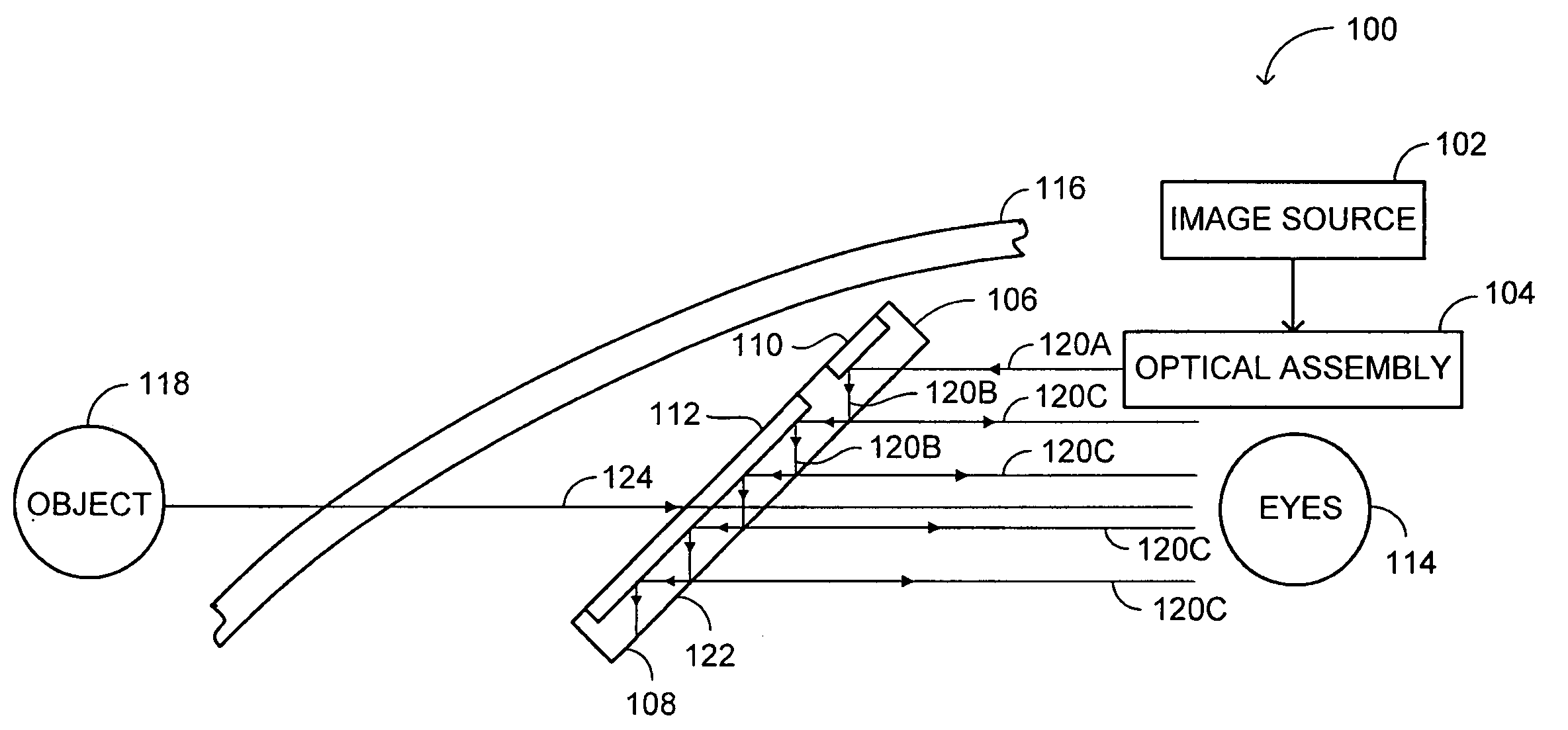
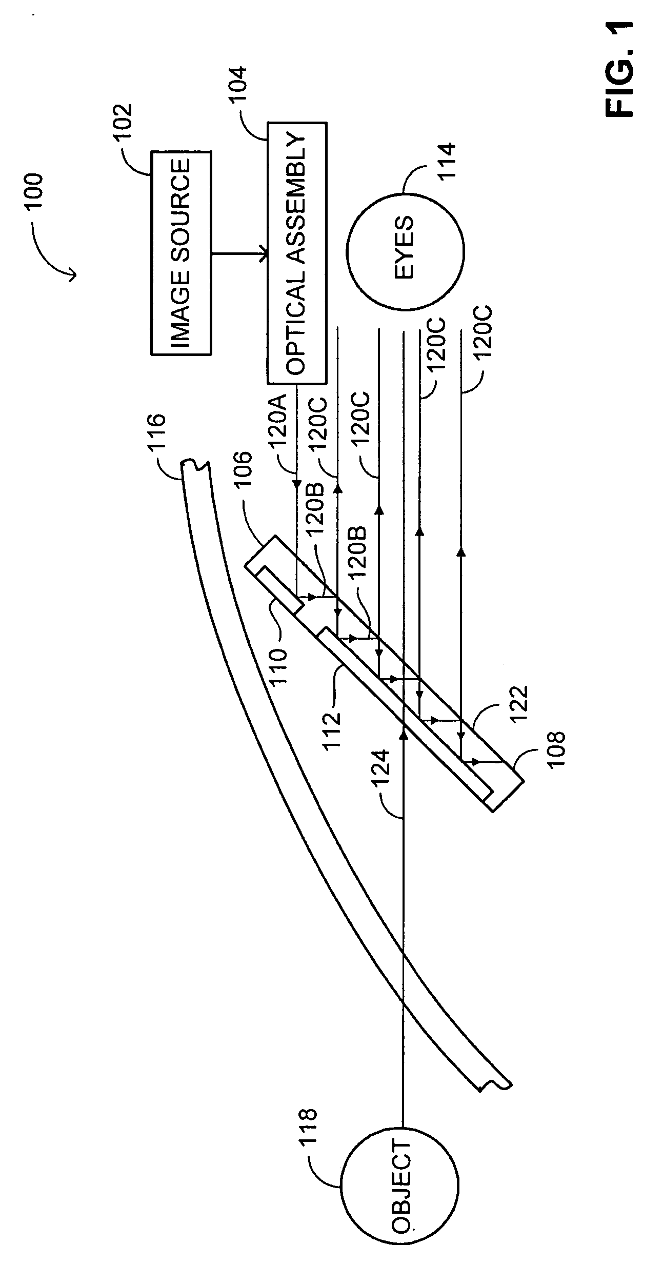
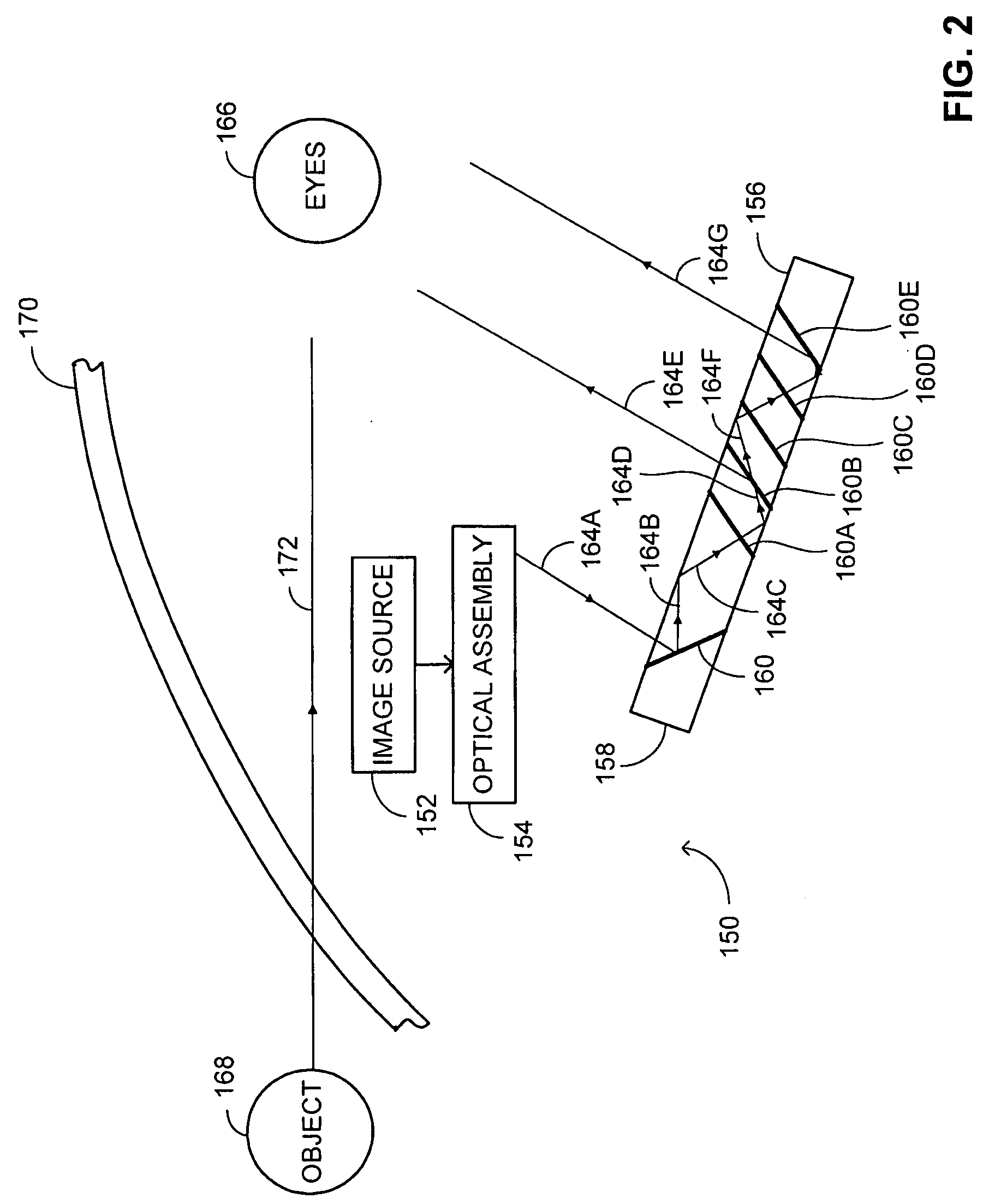
[0033] The disclosed technique overcomes the disadvantages of the prior art by providing a planar optical device which transforms and displays a plurality of virtual images whose focal points are substantially located at infinity and which are derived from a substantially small image source. The planar optical device can be located in the line of sight of an observer looking toward a scene substantially located at infinity, in which case the observer observes one virtual image at a time, against a scene image of the scene, and wherein the device operates as a head up display (HUD). Alternatively, the planar optical device can be located on an instrument panel of a cockpit of an aircraft or the driver compartment of a vehicle, in which case the planar optical device operates as a head down display (HDD).

[0034] Each of the virtual images is similar to an incident image produced by the substantially small image source, and the observer can observe a virtual image of the same incident ...


PUM


Abstract

System for displaying an incident image for an operator of a vehicle, the system including an optical assembly receiving the incident image from an image source, and a planar optical module optically coupled with the optical assembly, the optical assembly producing a collimated light beam according to the incident image, the planar optical module being located in a line of sight of the operator, the planar optical module displaying a set of output decoupled images, each of the output decoupled images being similar to the incident image, and each of the output decoupled images having a focal point substantially located at an infinite distance from the operator.

Description

RELATED APPLICATIONS [0001] This application is a continuation of PCT / IL2004 / 001094, filed Nov. 30, 2004, which claimed priority to Israeli patent application serial numbers IL 159159, filed Dec. 2, 2003 and IL 165376, filed Nov. 24, 2004; each of these applications is incorporated herein by reference.FIELD OF THE INVENTION [0002] The disclosed technique relates to display systems in general, and to methods and systems for displaying images in a vehicle, in particular. BACKGROUND OF THE INVENTION [0003] The driver of a ground vehicle uses the information displayed on the instrument panel, such as speed, fuel supply, engine revolutions per minute (RPM), and route finder, to drive the vehicle and navigate toward a desired location. The pilot of an aircraft depends on the data displayed on the instrument panel even more than the driver of the vehicle, in order to fly and navigate the aircraft, and particularly in order to take part in a midair combat, or to fire at a target on the grou...

Claims


Application Information

Patent Timeline
IPC IPC(8): G02B5/32G02B6/00G02B26/10G02B27/00G02B27/01
CPCG02B6/00G02B27/0101G02B2027/014
Inventor YOSHA, JACOBLEVI, BEZALEIDABBY-DVIR, TSADOCKFRIEDLAND, IGOR
Owner EL OP ELECTRO OPTICS INDS
Why Eureka
Try Eureka