Data relay apparatus and failure recovery method

a data relay and failure recovery technology, applied in data switching networks, instruments, frequency-division multiplexes, etc., can solve problems such as communication interruption over the whole network, increase in control load,

Inactive Publication Date: 2006-09-28
FUJITSU LTD
View PDF15 Cites 66 Cited by
  • Summary
  • Abstract
  • Description
  • Claims
  • Application Information

AI Technical Summary

Benefits of technology

[0011] It is an object of the present invention to at l

Problems solved by technology

Therefore, the load for the control increases.
Furthermore, a position of the block largely changes when the fail

Method used


Image

  • Data relay apparatus and failure recovery method
  • Data relay apparatus and failure recovery method
  • Data relay apparatus and failure recovery method

Examples


Embodiment Construction

[0032] Exemplary embodiments of a data relay apparatus and a failure recovery method according to the present invention are explained in detail below with reference to the accompanying drawings.

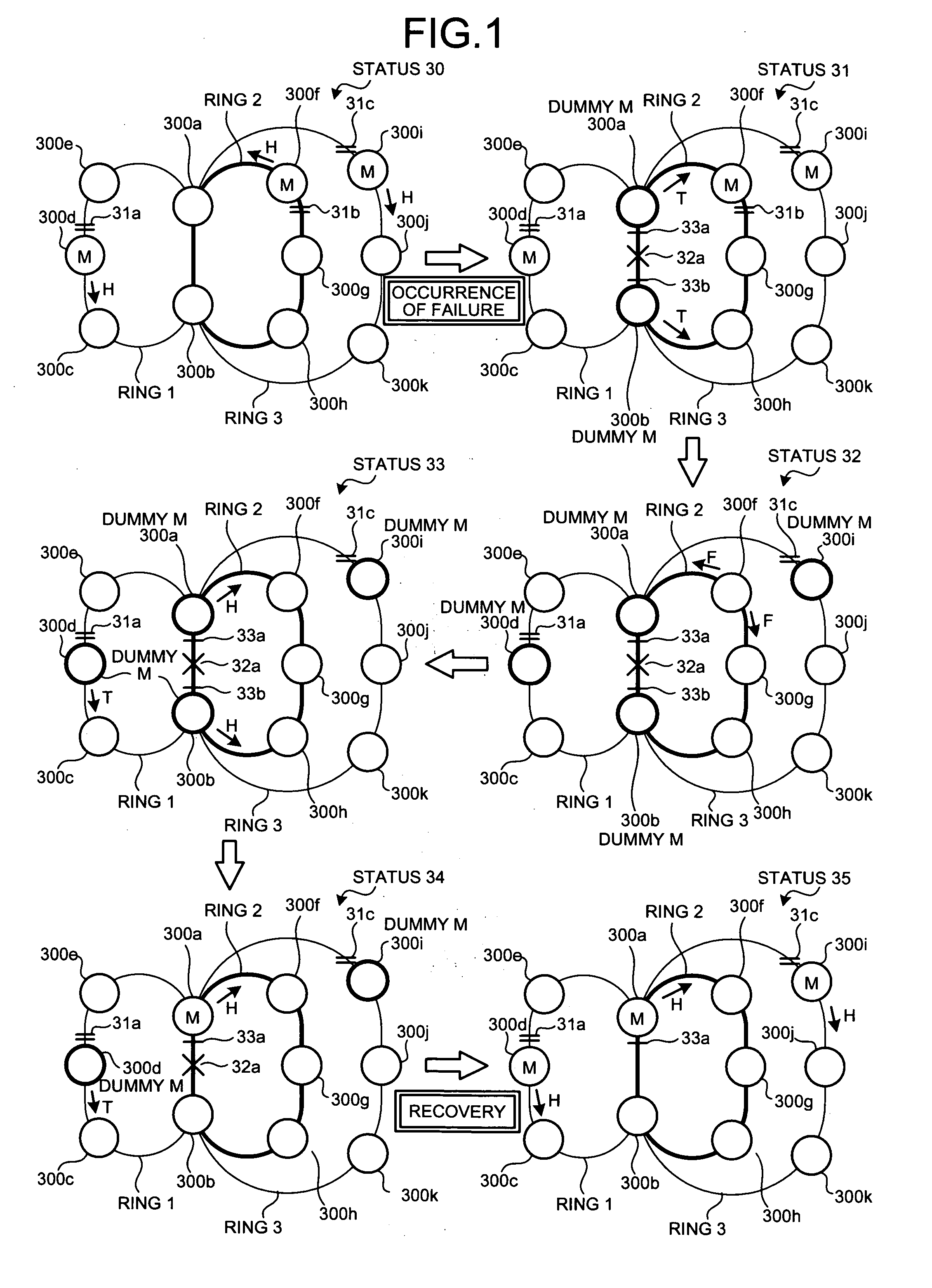
[0033] Some problems occurring when a failure occurs in a shared portion of a multi-ring network are explained below. FIG. 16 is a schematic for explaining some problems when a failure occurs in a shared portion of a ring.

[0034] The network shown in FIG. 16 has a multi-ring structure that shares a portion between a data relay apparatus 100a and a data relay apparatus 100b based on a ring 1 that includes the data relay apparatuses 100a and 100b and data relay apparatuses 100c, 100d, and 100e; and a ring 2 that includes the data relay apparatuses 100a and 100b and data relay apparatuses 100f, 100g, and 100h.

[0035] In normal operation, the data relay apparatus 100d that is a master (M) of the ring 1 sets a block 11a in a port thereof on the side of the data relay apparatus 100e, and causes a ...


PUM


Abstract

A data relay apparatus that recovers a failure in a network that shares a part of a plurality of rings and avoids occurrence of a loop path by providing a block in each of the rings includes a failure-notification-packet transmitting unit that transmits, when a failure is detected in a shared portion of a ring, a failure notification packet to a predetermined redundancy-providing ring; and a block setting unit that sets a block that blocks a main signal by passing through a control packet at a port where the failure is detected.

Description

BACKGROUND OF THE INVENTION [0001] 1. Field of the Invention [0002] The present invention relates to a technology for recovering a failure in a network that shares a part of a plurality of rings and avoids occurrence of a loop path by providing a block in each of the rings. [0003] 2. Description of the Related Art [0004] Recently, a network based on layer 2 using Ethernet (TM) is often used for building a large scale network such as a wide area network. The network using Ethernet (TM) has such advantages that its introduction cost is comparatively low but high-speed communication can be achieved. [0005] When a large scale network is built using Ethernet (TM), how to ensure redundancy is a significant matter. Because Ethernet (TM) has been developed specifically for a small scale network such as a local area network (LAN) and has therefore no redundancy that is required for the large scale network. [0006] One of technologies of providing redundancy to the network based on Ethernet (T...

Claims


Application Information

Patent Timeline
IPC IPC(8): H04J3/14H04J1/16
CPCH04J3/14H04L12/437
Inventor TOCHIO, YUJI
Owner FUJITSU LTD
Why Eureka
Try Eureka