
Protocol and system for firewall and NAT traversal for TCP connections

a protocol and protocol technology, applied in the field of peertopeer protocols, transmission control protocols, ip networks, etc., can solve the problems of inability of one tcp peer to discover another and establish a connection, and difficulty in deploying new ones,

Active Publication Date: 2006-09-28
NETGEAR INC
View PDF7 Cites 332 Cited by
  • Summary
  • Abstract
  • Description
  • Claims
  • Application Information

AI Technical Summary

Benefits of technology

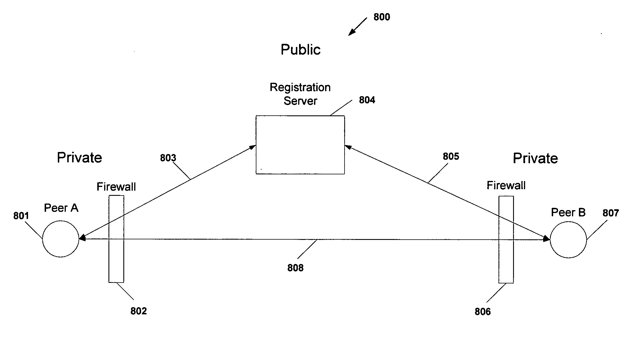
[0077] An embodiment of the present invention provides a system and a set of protocols that can be implemented in software or hardware to enable two TCP peers that exist behind one or more firewalls and NATs to automatically setup a true peer-to-peer TCP connection and exchange data. Embodiments of this invention allows the TCP connection between two TCP peers to traverse NATs and firewalls without making changes to the firewall or NAT devices or existing TCP-based applications. Embodiments of this invention can be used to traverse full cone, restricted cone, port restricted cone and symmetric NATs [1] as well as stateful firewalls. In order for a TCP connection to traverse a firewall and NAT, three operations must occur; the NAT needs to be traversed, the TCP peers need to be synchronized and a TCP connection needs to be established in each peer firewall.

Problems solved by technology

The most troublesome of those drawbacks is the fact that they break many existing transmission control protocol (TCP) / Internet Protocol (IP) applications, and make it difficult to deploy new ones such as multimedia applications, file sharing and the like.
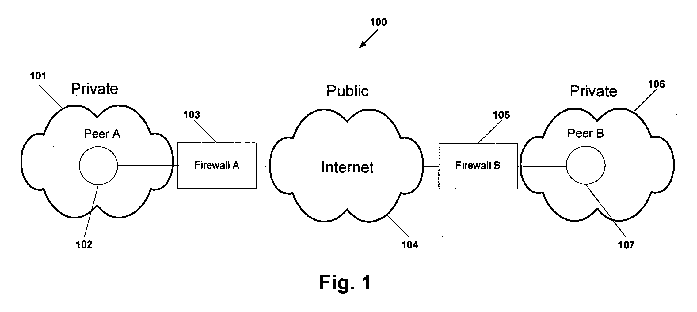
Together, NATs and firewalls conceal the identity of IP clients (i.e., peers) and block transmission control protocol (TCP) call setup requests making it impossible for one TCP peer to discover another and establish a connection.

Method used


Image

  • Protocol and system for firewall and NAT traversal for TCP connections
  • Protocol and system for firewall and NAT traversal for TCP connections
  • Protocol and system for firewall and NAT traversal for TCP connections

Examples


Embodiment Construction

[0090] In the following description of preferred embodiments, references are made to the accompanying drawings, which form a part hereof and in which are shown, by way of illustration, specific embodiments in which the invention may be practiced. It is to be understood that other embodiments may be utilized and structural changes may be made without departing from the scope of the preferred embodiments of the present invention.

[0091] The physical environment in which this invention may be applied is shown in FIG. 1. The environment 100 consists of two TCP peers (Peer A 102 and Peer B 107) each existing behind a NAT and firewall 103, 105 on a private network 101,106 and connected by any IP network (public) 104, which may be the Internet, and the like. Embodiments of this invention may also be applied if Peer A is behind and NAT and firewall and Peer B is not, as well as if Peer B is behind a NAT and firewall and Peer A is not. Embodiments of this invention may also be applied if Pee...


PUM


Abstract

Firewalls and network address translators (NAT) provide many advantages for client and the Internet itself, however, these devices break many existing transmission control protocol (TCP) / Internet Protocol (IP) applications, since they conceal the identity of IP clients (i.e., peers) and block transmission control protocol (TCP) call setup requests. Firewalls and NATs make it impossible for one TCP peer to discover another and establish a connection. Embodiments of this invention provides a system and a protocol to enable two TCP peers that exist behind one or more firewalls and NATs to automatically setup a true peer-to-peer TCP connection and exchange data without making changes to the firewall or NAT devices or existing TCP-based applications. In embodiments of this invention, the synchronization between the blind TCP peers is achieved using a system that consists of a registration server, an agent application, and a virtual network interface that together relay and replicate the control signals between the two TCP peers. In addition, embodiments of this invention are also used to traverse the NAT and establish a bi-directional peer-to-peer TCP connection in the firewall.

Description

CROSS-REFERENCE TO RELATED APPLICATION [0001] This application is a non-provisional application claiming priority from U.S. Provisional application No. 60-659,556 previously filed with the U.S.P.T.O. on Mar. 3, 2005 by the same inventor. The entirety of the application is incorporated by reference herein.BACKGROUND OF INVENTION [0002] 1. Field of Invention [0003] Embodiments of this invention relate to the field of Internet Protocol (IP) networks, Transmission Control Protocol (TCP), Peer-to-Peer protocols and more particularly to the traversal of firewalls and network address translators (NATs) for TCP connections. [0004] 2. Discussion of Related Art [0005] The Internet has been designed around a client server model where many clients initiate a connection to communicate with a single server, for example many web-browsers accessing a web-server, which is know as a client-server model and protocols to support this model have been develop such as HTTP, FTP, etc. However, this model i...

Claims


Application Information

Patent Timeline
IPC IPC(8): G06F15/16
CPCH04L63/029H04L69/16
Inventor CAPONE, JEFFREY M.
Owner NETGEAR INC
Learn More