Apparatus for combining beams from repetitively pulsed lasers along a common path

Inactive Publication Date: 2006-09-28
COHERENT GMBH
View PDF14 Cites 5 Cited by
  • Summary
  • Abstract
  • Description
  • Claims
  • Application Information

AI Technical Summary

Problems solved by technology

Maximum average power can be limited because the laser cannot generate sufficient energy per pulse, or cannot deliver pulses having sufficient energy at a sufficiently high pulse-repetition frequency (PRF).

Method used


Image

  • Apparatus for combining beams from repetitively pulsed lasers along a common path
  • Apparatus for combining beams from repetitively pulsed lasers along a common path
  • Apparatus for combining beams from repetitively pulsed lasers along a common path

Examples


Embodiment Construction

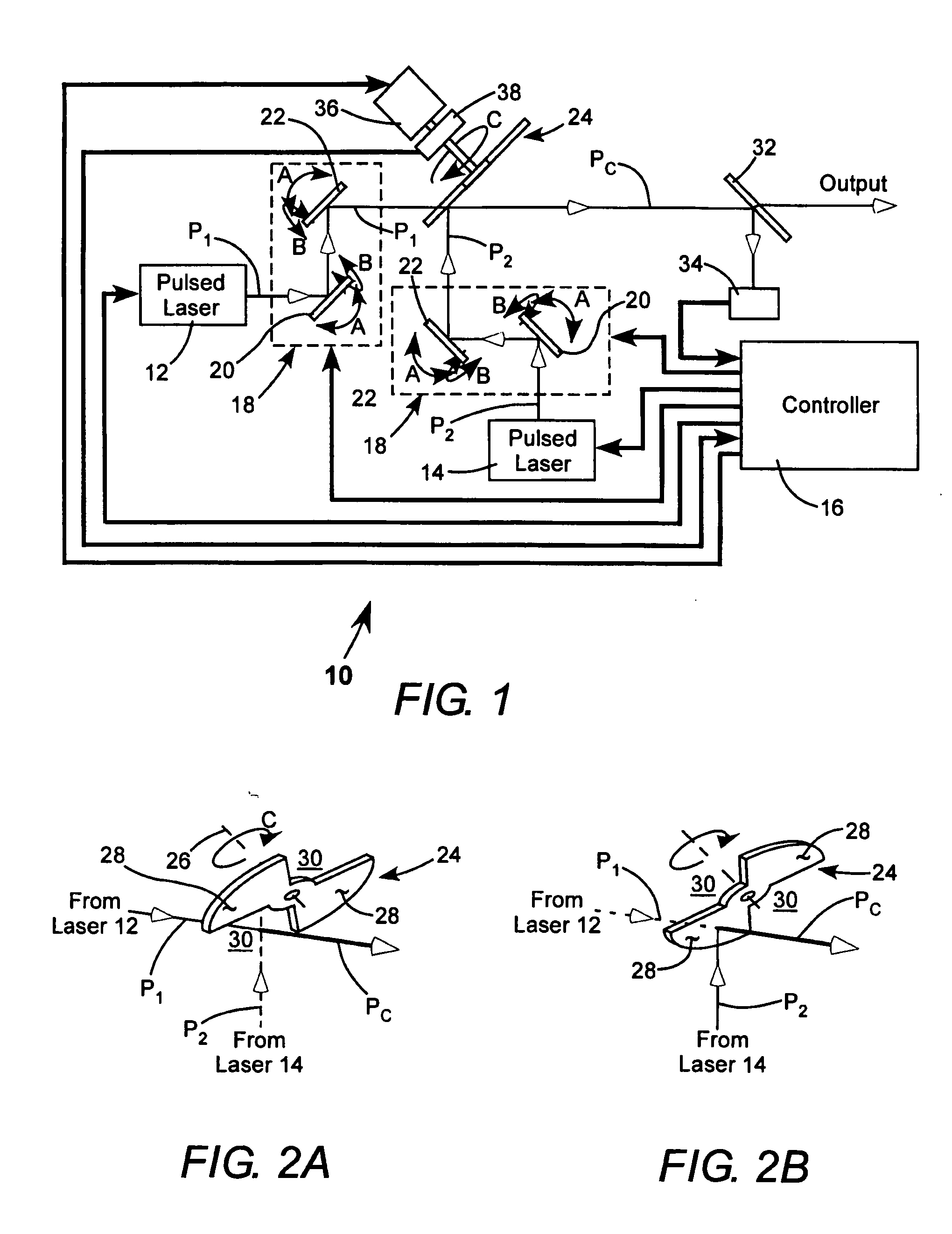
[0016] Referring now to the drawings, wherein like components are designated by like reference numerals, FIG. 1 schematically illustrates one preferred embodiment 10 of laser-beam combining apparatus in accordance with the present invention. In FIG. 1, beam paths are indicated by fines lines, with the propagation direction along the paths indicated by open arrowheads. Electronic interconnections are designated by bold lines with the direction of communication indicated by solid arrowheads. It should be borne in mind that optical pulses are traveling along the beam paths rather than continuous radiation, however, a pulse of even only 20 nanoseconds (ns) duration will have a “length” along a beam path of more than 6.5 meters (m). Accordingly, the “beam” representation of pulses is appropriate here. It should also be borne in mind, however, that the duty cycle of pulses is usually only a fraction of one-percent. Accordingly, at pulse repetition rates of about 10 kilohertz (kHz) there w...


PUM


Abstract

Two pulse sequences are delivered by two lasers. A rotating segmented mirror having one or more reflective areas and one or more transmissive areas is rotated synchronously with the delivery of the pulse sequences to transmit pulses from one sequence, and to reflect pulses from the other sequence at intervals.

Description

PRIORITY CLAIM [0001] This application claims the priority of U.S. Provisional Application No. 60 / 664,788, filed Mar. 24, 2005 the disclosure of which is incorporated by reference.TECHNICAL FIELD OF THE INVENTION [0002] The present invention relates in general to operating repetitively pulsed lasers. The apparatus relates to temporally interleaving pulse sequences from two such repetitively pulsed lasers along a common path. DISCUSSION OF BACKGROUND ART [0003] In certain applications of pulsed laser radiation, a specific wavelength of radiation, characteristic of a certain type of laser, may be preferred, or may even be necessary. In such applications, the maximum average power in a pulse sequence from a single one of that type of laser may often be less than would be desirable for that application, for example for providing a desired manufacturing throughput. Maximum average power can be limited because the laser cannot generate sufficient energy per pulse, or cannot deliver pulses...

Claims


Application Information

Patent Timeline
IPC IPC(8): H01S3/10H01S3/08
CPCG02B26/0816H01S3/005
Inventor WIESSNER, ALEXANDER O.SCHROEDER, THOMAS
Owner COHERENT GMBH
Why Eureka
Try Eureka