Sample holder and microscope assembly

a microscope and sample technology, applied in the field of sample holder, can solve the problems of reducing the sample throughput in the sample examination, not being able to ensure high throughput, and not being able to achieve the effect of ensuring high throughput, simple transportation and handling of incubation units, and reliable warming treatmen

Inactive Publication Date: 2006-09-28
EURO LAB FUER MOLEKULARBIOLOGIE EMBL
View PDF9 Cites 4 Cited by
  • Summary
  • Abstract
  • Description
  • Claims
  • Application Information

AI Technical Summary

Benefits of technology

[0008] In a manner according to the invention it has been recognized that a special development of the base frame on its upper surface realizes the above objective in a surprisingly simple manner. For this, the base frame comprises on its upper surface in concrete terms a coupling area for at least one additional functional element. Thereby, it is made possible to expose the sample or samples to desired treatment measures in a simple manner. These could, for example, be a warming treatment or a cooling treatment, where then at least one heating and/or cooling device is to be coupled with the base frame at its coupling area. This permits the development of a sample holder as a functional unit to provide desired additional functions which can be exercised along with the basic function

Problems solved by technology

With the known sample holders and heating devices it is problematic that they are ultimately not suitable to ensure high throughput of sample examinations.
The known sample holders must be moved and positioned by hand, and during transport from the microscope to, for example, ano

Method used


Image

  • Sample holder and microscope assembly
  • Sample holder and microscope assembly
  • Sample holder and microscope assembly

Examples


Embodiment Construction

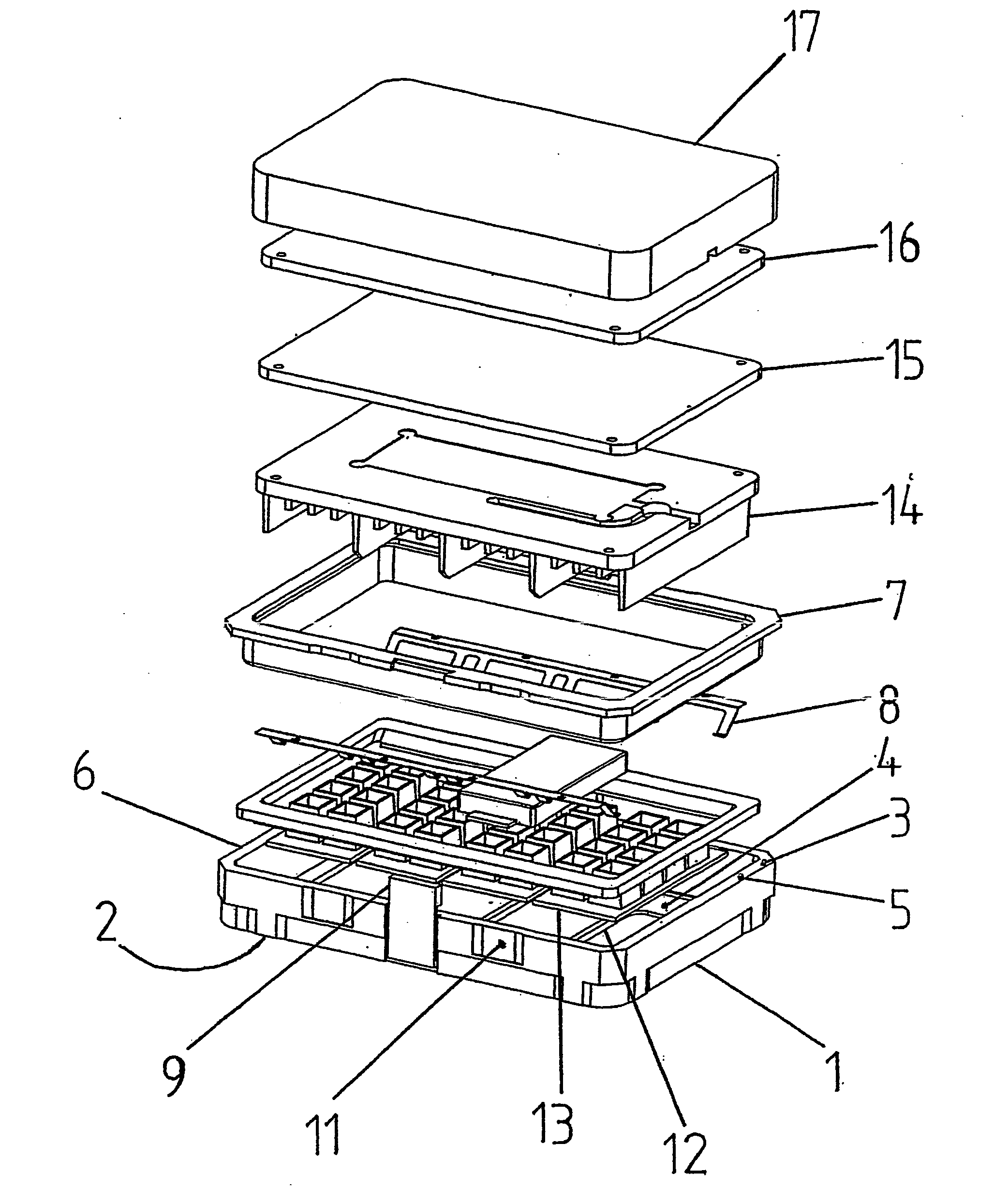
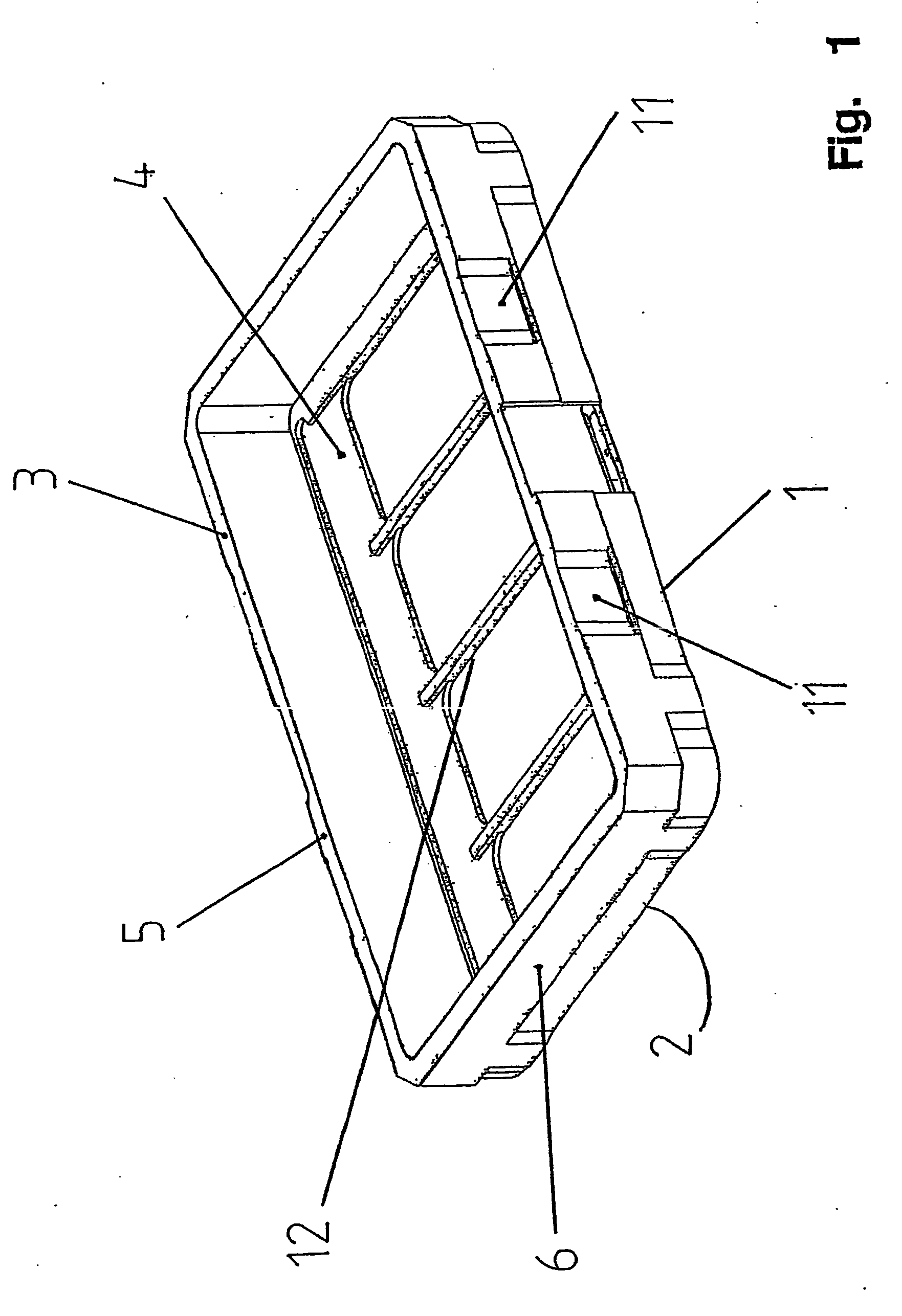
[0042]FIG. 1 shows an embodiment of a sample holder according to the invention in a perspective side view. The sample holder comprises a base frame 1 which in turn comprises an underside 2, an upper surface 3, and a receiving area 4 for samples. The receiving area 4 is divided into four subsections by means of three bars. In regard to a high sample throughput with means which are simple from the standpoint of construction, the base frame 1 comprises on its upper surface 3 a coupling area 5 for at least one additional functional element. A functional element of this type could, for example, be formed by a cover, a heating plate, or a cooling plate.

[0043] The base frame 1 comprises side walls 6 connected to one another, where the coupling area 5 is formed on the upper ends of the side walls 6.

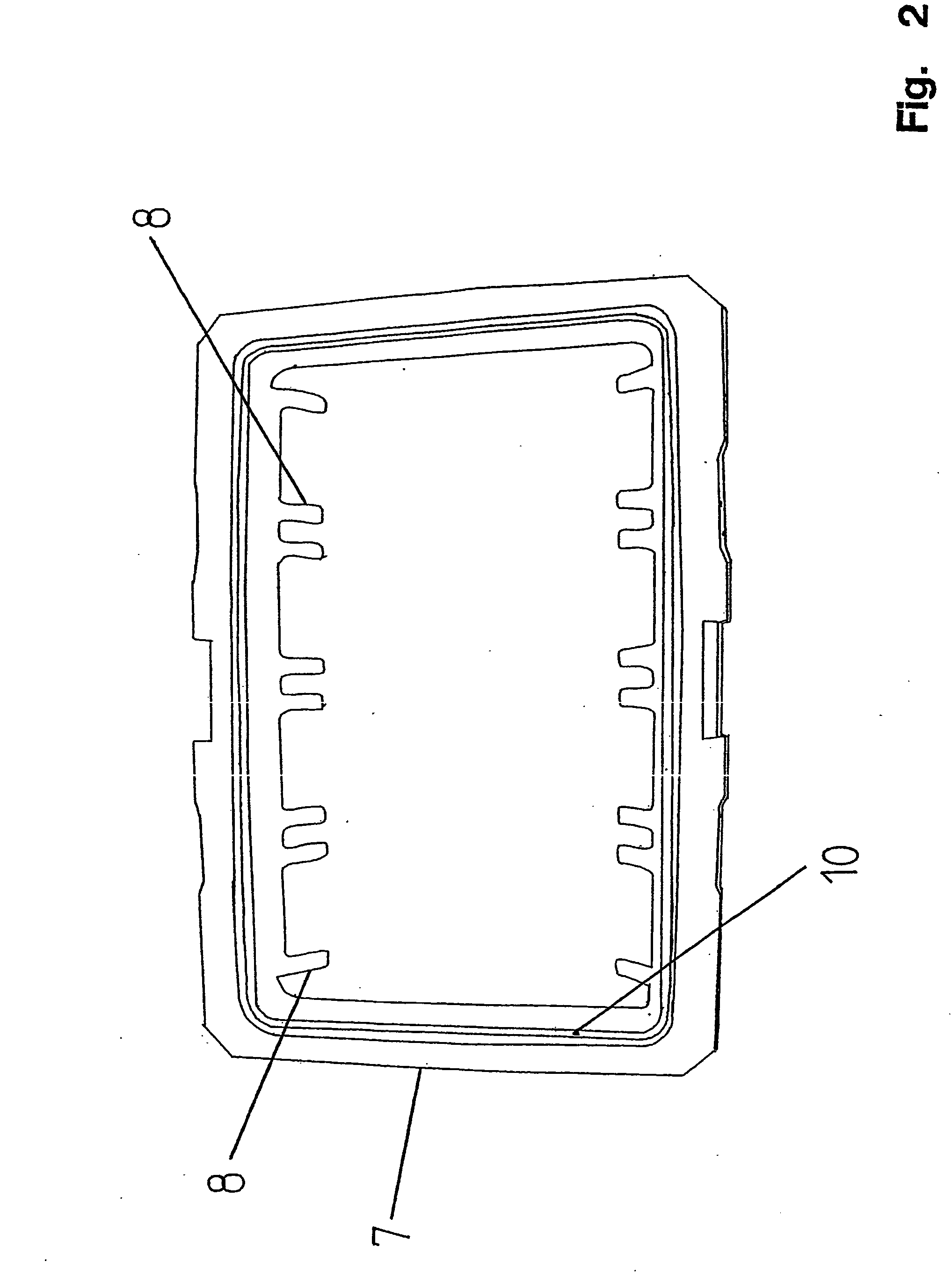
[0044] The base frame 1 comprises a roughened grip area 11 for a more secure hold with, for example, an automated needle gripper. To limit heat transfer, the base frame 1 comprises additional p...


PUM


Abstract

A sample holder for handling samples to be viewed under a microscope, and which comprises a base frame 1 provided with a lower surface 2, an upper surface 3, and at least one receiving area 4 for at least one sample. In order to facilitate examination of a large number of samples, the sample holder is provided with a coupling area 5 on its upper surface for receiving at least one other functional element, such as a sample fixing element, a heating or cooling plate, or a cover.

Description

CROSS REFERENCE TO RELATED APPLICATION [0001] The present application is a continuation of international application PCT / DE2004 / 002208, filed 4 Oct., 2004, and which designates the U.S. The disclosure of the referenced application is incorporated herein by reference.BACKGROUND OF THE INVENTION [0002] The present invention relates to a sample holder, in particular for handling samples to be viewed under a microscope. The sample holder has a base frame, and the base frame comprises an underside, an upper side, and at least one receiving area for at least one sample. Furthermore, the present invention relates to a microscope assembly with a corresponding sample holder. [0003] Sample holders of the type referred to above are known from practice and exist in a variety of embodiments and sizes. Sample holders of this type are most frequently formed by a frame-like rack into which samples can be inserted. Object holders, chamber cover slips, or so-called chamber slides can serve as samples...

Claims


Application Information

Patent Timeline
IPC IPC(8): B01L3/00B01L9/00
CPCB01L9/52B01L2200/025B01L2200/028B01L2300/0609B01L2300/0822B01L2300/1827
Inventor LIEBEL, URBANPEPPERKOK, RAINERWINKLER, SIEGFRIEDSCHAAR, HELMUTDILLING, WOLFGANG
Owner EURO LAB FUER MOLEKULARBIOLOGIE EMBL
Why Eureka
Try Eureka