
Optical analytic measurement device for fluorescence measurements in multisample carriers

Inactive Publication Date: 2005-10-06
CYBIO AG
View PDF7 Cites 24 Cited by
  • Summary
  • Abstract
  • Description
  • Claims
  • Application Information

AI Technical Summary

Benefits of technology

[0037] Further, it is advantageous when the excitation beam path and the evaluation beam path are directed to the transparent bottom of the multisample carrier and a dispensing device or pipetting device is provided above the multisample carrier for adding liquid at the same time that measurements of the emission of the samples of the multisample carrier are constantly being carried out. In the measuring position, test substance from a microplate, the so-called compound plate, can be transferred to the assay plate particularly by use of a simultaneous pipetter with, e.g., 96 or 384 pipetting tips.
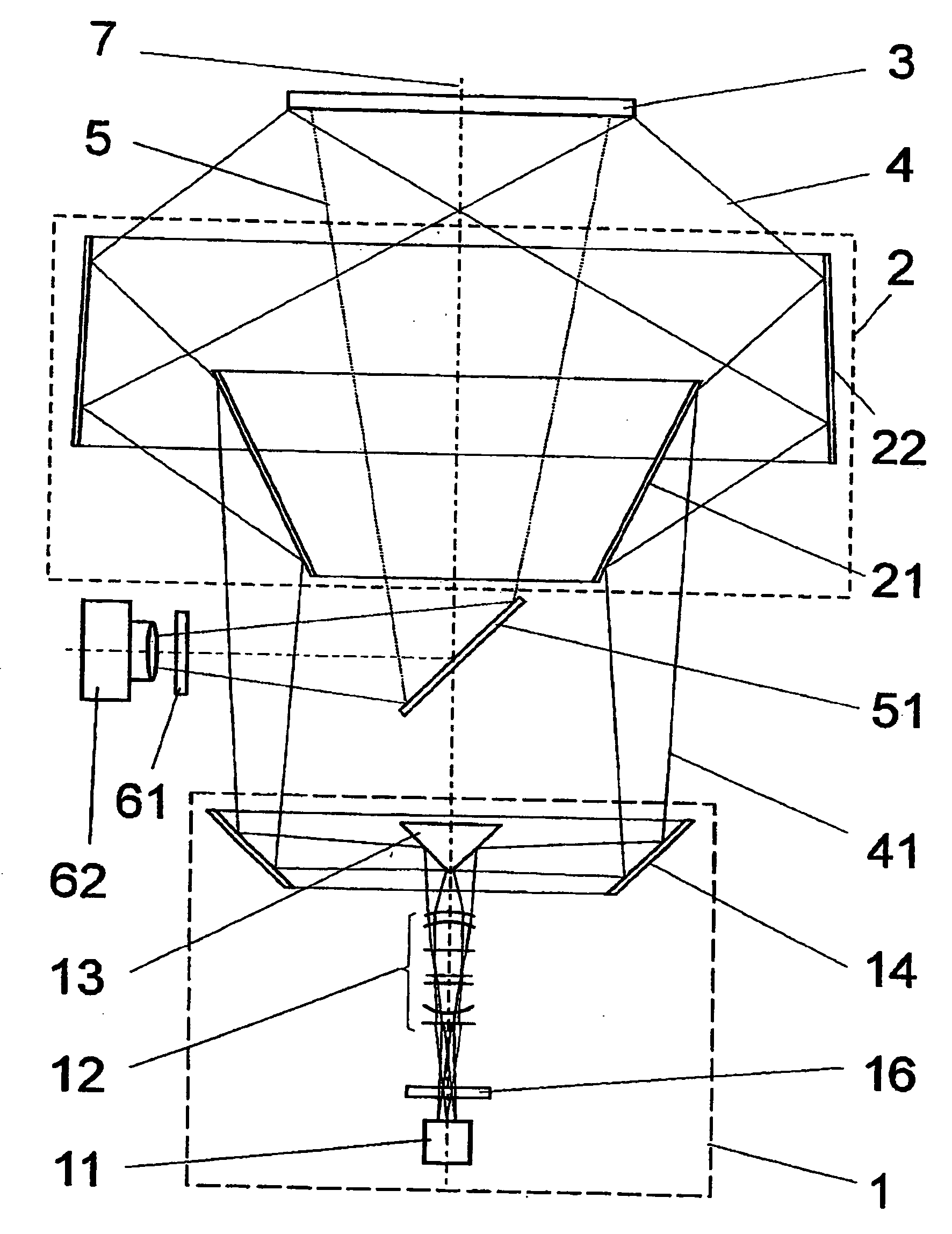
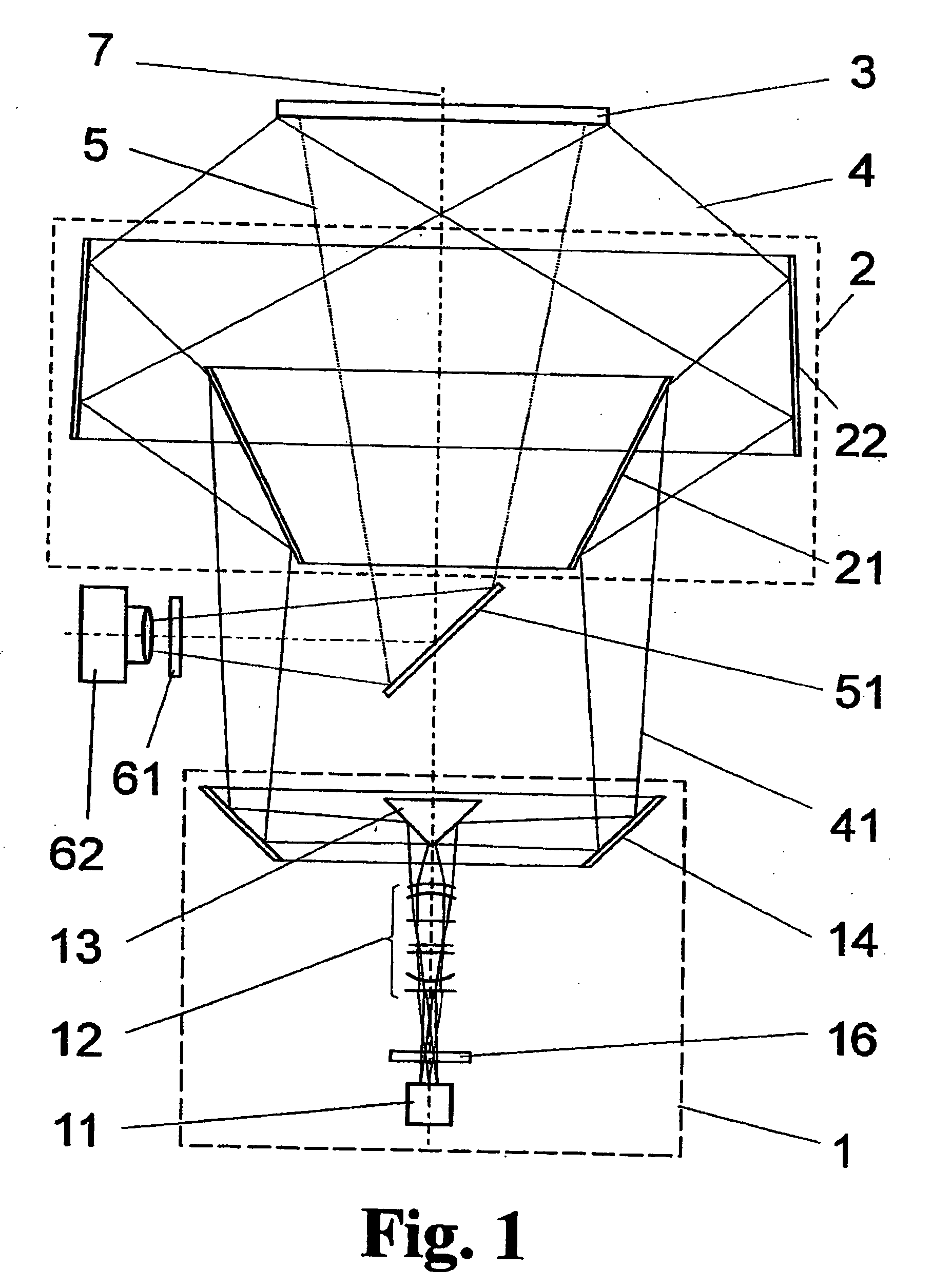
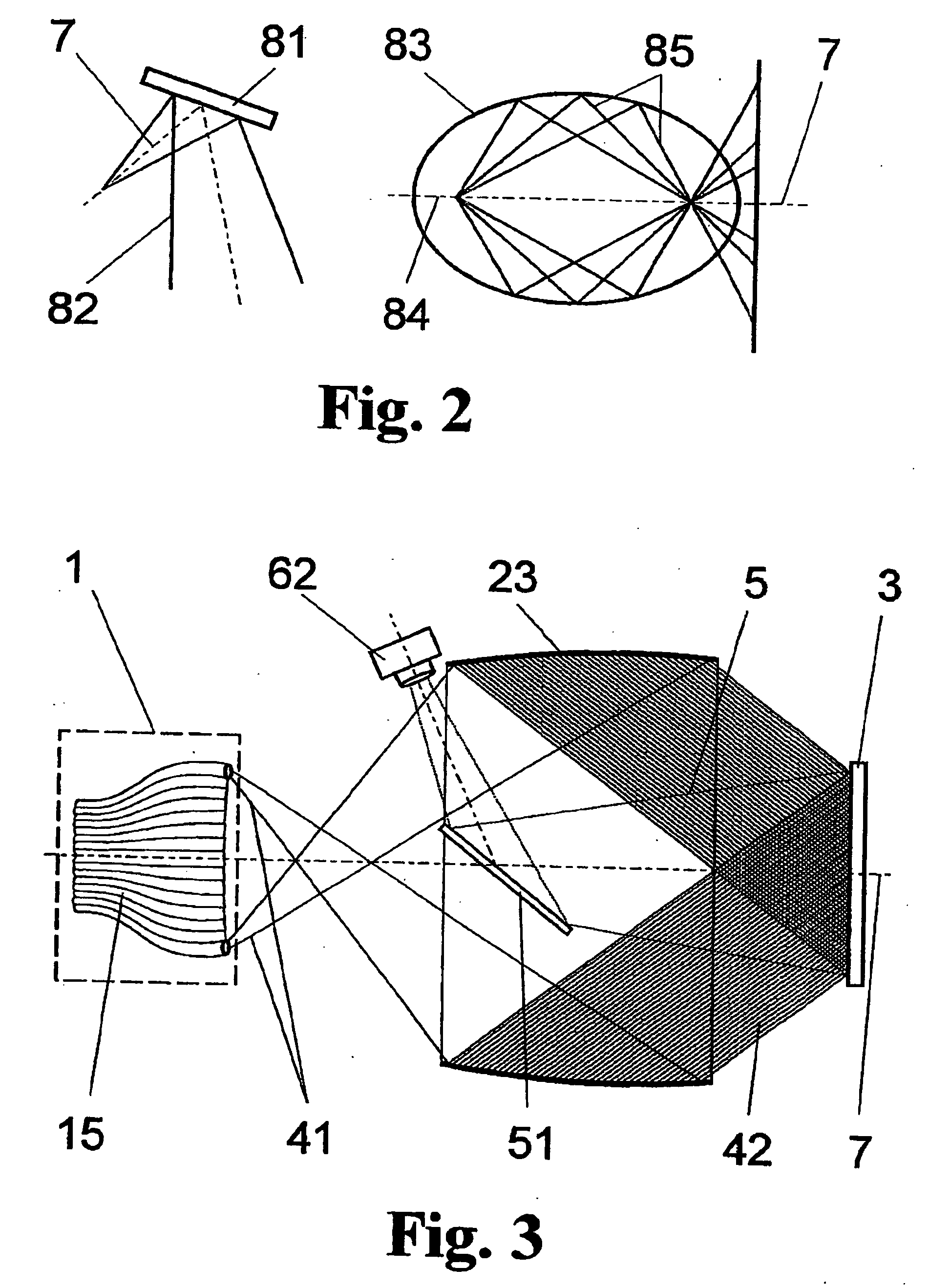
[0040] The required ring light bundle can be generated in different ways. In this connection, it must be ensured that an intensive bundle which is symmetric with respect to rotation around the optical axis and homogeneous with respect to light distribution is generated in the form of a slightly divergent truncated cone shape impinging on the ring mirror. In all cases, the optical axes for excitation and detection are identical and correspond to the mean perpendiculars of the microplate and to the axis of symmetry of the entire optical construction. The rotationally symmetric ring mirrors used for illumination are zones of the outer surfaces of bodies of revolution and can be internally mirror-coated conical surfaces, ellipsoid surfaces, paraboloid surfaces, hyperboloid surfaces or surfaces of other rotating curves. The incident angles realized on the microplate reliably prevent reflections of the excitation light originating from the bottom surface of the microplate from reaching the camera objective in that the excitation and detection channels do not share any optical components and nevertheless have a common optical axis. When using ring mirrors as zones of rotationally symmetric outer surfaces of rotating curves, a parallel beam guidance is achieved on the microplate (object-side parallel beam path) and the incident angle is accordingly kept constant over the entire microplate.
[0043] Further, the invention allows one or more liquids to be added for an assay without substantially increasing the total measuring period by liquid handling.
[0047] For the HTS regime in particular, the advantage of multiplexing is also gained by means of this parallel measurement by a CCD camera and a high sample throughput is accordingly achieved in spite of an appreciably increased measuring time per well.

Problems solved by technology

The dispensing position is located before the measurement position spatially so that it is necessary to displace the microplate after adding liquid in order to measure the well in which the liquid has been dispensed; therefore, a time delay occurs.
However, a procedure of this kind requires switching intervals of several seconds each and is not suited to HTS.
The disadvantage in this arrangement consists in that there is no separation of the excitation beam from the readout beam, i.e., tube brightening exists due to the shared use of the front lens and generates a considerable proportion of the background light.
Troublesome tube brightening and background fluorescence from the supernatant sample are also inevitable in this case.
The disadvantage of the system is that there is a separate microobjective for each well so that when the microplate format changes (with an increased quantity of wells) the system malfunctions or special masks which disadvantageously limit the illumination efficiency would have to be used.
However, the use of absorbent dyes is also problematic because, on the one hand, their biochemical reaction is unclear and, on the other hand, the absorption in the centrate is incomplete and can ultimately also have an (undesirable) effect in the cell layer.

Method used


Image

  • Optical analytic measurement device for fluorescence measurements in multisample carriers
  • Optical analytic measurement device for fluorescence measurements in multisample carriers
  • Optical analytic measurement device for fluorescence measurements in multisample carriers

Examples


application example

[0100] In an embodiment form of the invention, according to FIG. 6, using two (pulsed) light sources 11 with defined excitation wavelengths, a quantitative determination of determined ions, e.g., calcium, can also be undertaken as will be explained more precisely in the following example (Fura analysis).

[0101] In cell biology, the transient intracellular calcium concentration is of interest because it supplies information about the viability of a cell. The fluorescent dye, Fura III, makes it possible to quantify the concentration of calcium when excited at 340 nm and 380 nm and the emission is observed in each instance at 520 nm. The device shown in FIG. 6 is constructed in such a way that it also permits this Ca measurement. The requirements are met by two strobe lamps—adjusted to 340 nm and 380 nm, respectively—and camera observation at 520 nm. The quotient of the two signals which are measured roughly simultaneously represents the Ca concentration (when the signal remains consta...


PUM


Abstract

The invention is directed to a device for optical analytic measurement in a multisample carrier, particularly for measuring fluorescence or bioluminescence. The object of the invention, to find a novel possibility for measuring fluorescence or luminescence in multisample carriers, wherein, during excitation of all of the wells, the secondary radiation of each well is measured simultaneously without impermissible contributions of background radiation which falsify the characteristic emission of the sample material, is met according to the invention in that the excitation light from a light source unit is directed on the multisample carrier coaxially in a ring-shaped manner around an optical axis wherein the optical axis is oriented in direction of a surface normal of the multisample carrier and coaxial to the direction of the readout beam path, and a ring mirror unit with at least one curved ring mirror, which is arranged coaxial to the optical axis in such a way that the excitation light; illuminates the multisample carrier homogeneously on all sides at an oblique incident angle, is provided for orientation of the excitation light on the multisample carrier.

Description

CROSS-REFERENCE TO RELATED APPLICATION [0001] This application claims priority of German Application No. 10 2004 016 361.8, filed Apr. 1, 2004, the complete disclosure of which is hereby incorporated by reference. BACKGROUND OF THE INVENTION [0002] a) Field of the Invention [0003] The invention is directed to a device for optical analytic measurement in a multisample carrier, particularly for measuring fluorescence or bioluminescence, in which a plurality of samples are read out simultaneously for optical analysis in addition to the reaction process and excitation process. The invention is preferably applicable for analysis of biochemical or cell-based assays which require dispensing liquids into wells of the multisample carrier together with optical excitation and simultaneous readout of the samples. [0004] b) Description of the Related Art [0005] Particularly in biochemistry and pharmacology, it is necessary to test as many different substances as possible in microtitration plates...

Claims


Application Information

Patent Timeline
IPC IPC(8): G01N21/64G01N21/76
CPCG01N21/6452G01N21/6456G01N2021/6463G01N21/763G01N21/6486
Inventor WULF, JUERGENDIETZSCH, EBERHARDMOORE, THOMAS
Owner CYBIO AG
Learn More