Coaxial cable end-processing structure, coaxial cable shielding terminal and press-fastening apparatus

a technology of coaxial cable and end-processing structure, which is applied in the direction of electrical equipment, antenna connectors, and connections effected by permanent deformation, etc. it can solve the problems of affecting operation efficiency, increasing the number of components, and affecting operation efficiency, so as to achieve easy operation, reduce the number of components, and improve the effect of tensile strength

Inactive Publication Date: 2006-09-28
YAZAKI CORP
View PDF9 Cites 12 Cited by
  • Summary
  • Abstract
  • Description
  • Claims
  • Application Information

AI Technical Summary

Benefits of technology

[0036] In the invention according to (6), by providing the insulating sheath-holding portion, there is achieved an advantage that the tensile strength can be more positively maintained.
[0037] In the invention according to (7), there is achieved an advantage that there can be provided the coaxial cable end-processing structure in which the operation can be easily carried out, and besides the number of the component parts is reduced, and furthermore the high-frequency characteristics and the tensile strength can be maintained.
[0038] In the invention according to (8), there is achieved an advantage that the annular projecting braid portion can easily be electrically and mechanically connected to the coaxial cable shielding terminal.
[0039] In the inve

Problems solved by technology

Therefore, the conventional connecting structure has a problem that the efficiency of the operation is affected since the cumbersome operation must be carried out.

Method used


Image

  • Coaxial cable end-processing structure, coaxial cable shielding terminal and press-fastening apparatus
  • Coaxial cable end-processing structure, coaxial cable shielding terminal and press-fastening apparatus
  • Coaxial cable end-processing structure, coaxial cable shielding terminal and press-fastening apparatus

Examples


first embodiment

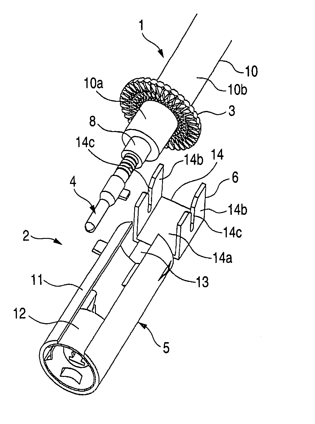
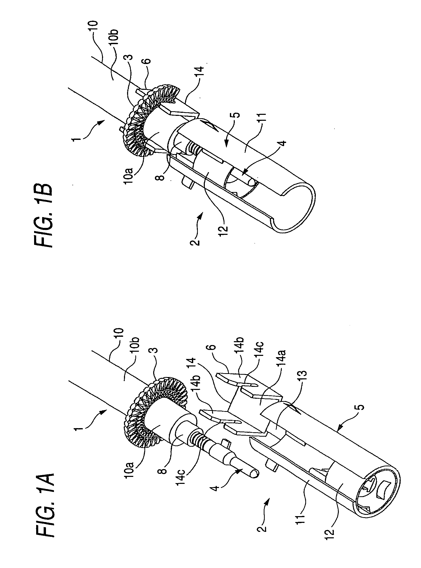
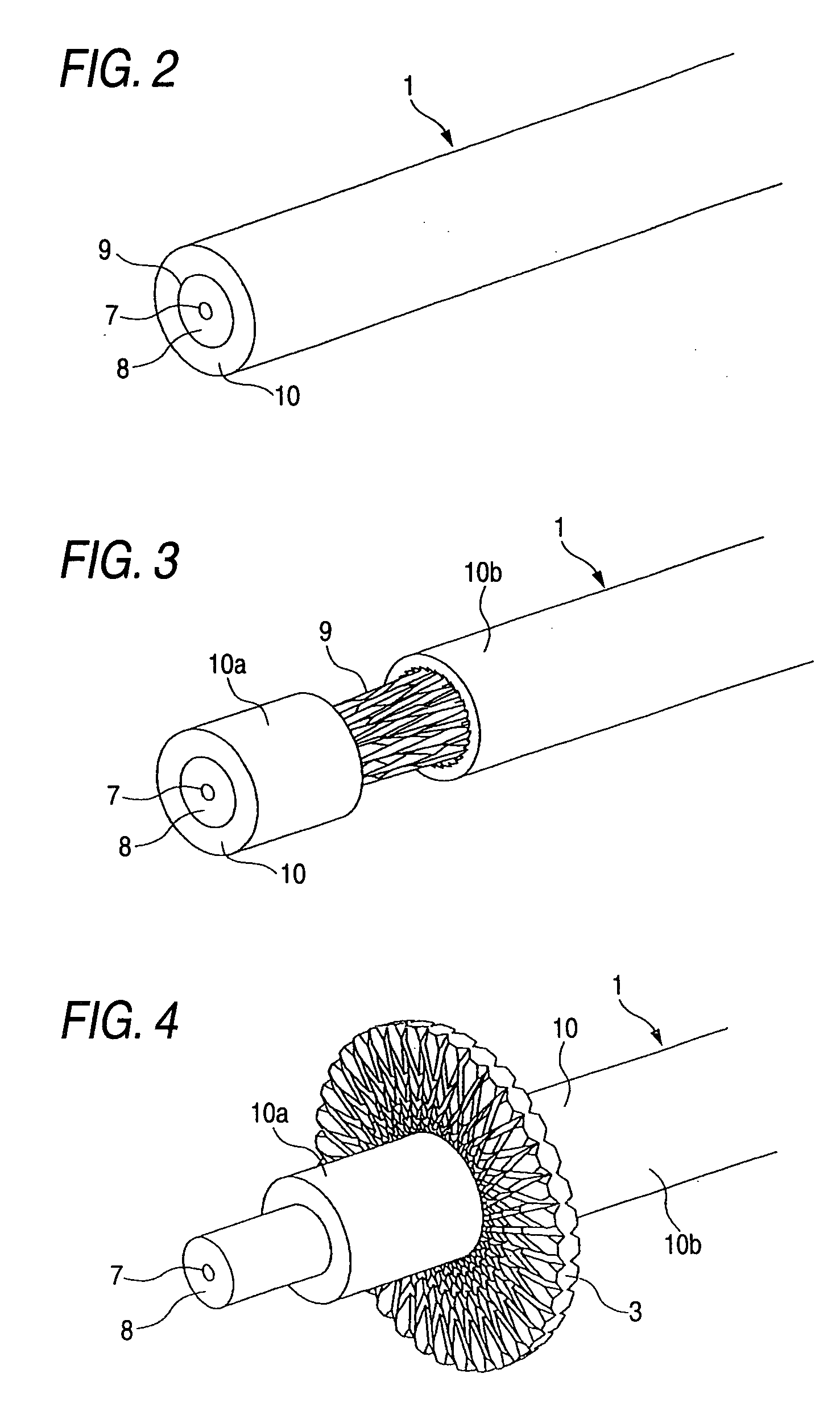
[0071]FIGS. 1A and 1B show a coaxial cable end-processing structure and a coaxial cable shielding terminal which are provided in accordance with the first embodiment of the invention, and FIG. 1A is a perspective view showing a condition before a connecting operation is effected, and FIG. 1B is a cross-sectional view showing a condition after the connecting operation is effected. FIG. 2 is a perspective view of a coaxial cable which is not yet processed, FIG. 3 is a perspective view of the coaxial cable, showing a condition in which an intermediate portion of an insulating sheath of the coaxial cable is removed, FIG. 4 is a perspective view of the coaxial cable, showing a condition in which an annular projecting braid portion is formed on the coaxial cable, FIG. 5 is a perspective view showing a condition in which a core conductor is exposed, FIG. 6 is a perspective view showing a condition in which an inner terminal is mounted on the core conductor, FIG. 7 is a perspective view sho...

second embodiment

[0085] Next, a coaxial cable end-processing structure and a coaxial cable shielding terminal, provided in accordance with the second embodiment of the invention, will be described with reference to FIGS. 10 to 12.

[0086]FIG. 10 is a perspective view of this embodiment, showing a condition before a coaxial cable is connected to the coaxial cable shielding terminal, FIG. 11 is a perspective view showing a condition in which an annular projecting braid portion is set on a braid fixing portion, and FIG. 12 is a perspective view showing a condition in which the braid fixing portion is pressed to be connected by press-clamping to the annular projecting braid portion.

[0087] In the end processing structure of this embodiment, the annular projecting braid portion 3, formed at the coaxial cable 1, is fixed so as to be connected to the braid fixing portion 6′ of the shielding terminal 5 of a coaxial connector 2 as in the above embodiment (Those portions, basically identical to the correspondi...

third embodiment

[0094] Next, a coaxial cable end-processing structure and a coaxial cable shielding terminal, provided in accordance with the third embodiment of the invention, will be described with reference to FIGS. 13 to 15.

[0095]FIG. 13 is a schematic perspective view showing the third embodiment of the invention, FIG. 14 is a schematic perspective view showing a condition in which a braid fixing portion is press-deformed to be connected by press-clamping to an annular projecting braid portion, and FIG. 15 is a cross-sectional view taken along the line XV-XV of FIG. 14.

[0096] In the end processing structure of this embodiment, the annular projecting braid portion 3, formed at a coaxial cable 1, is fixed so as to be connected to the braid fixing portion 6″ of a shielding terminal 5 of a coaxial connector 2 as in the above two embodiments (Those portions, basically identical to the corresponding portions of the above embodiments, will be designated by identical reference numerals, respectively...


PUM


Abstract

An intermediate portion of an insulating sheath of a coaxial cable is removed, and a first insulating sheath portion is drawn toward a second insulating sheath portion, so that a braid is projected into an annular shape outwardly from an interval between opposed ends of the first and second insulating sheath portions to form an annular projecting braid portion, and this annular projecting braid portion is fixed so as to be connected to a portion (that is, a braid fixing portion) of a coaxial cable shielding terminal for connection to an end portion of the coaxial cable. This connecting and fixing operation is effected by press-contacting or press-clamping.

Description

BACKGROUND OF THE INVENTION [0001] 1. Field of the Invention [0002] This invention relates to a coaxial cable end-processing structure, a coaxial cable shielding terminal forming a coaxial connector, and a press-fastening apparatus having a press clamping-purpose press-fastening blade for press-deforming a press-clamping portion of a coaxial cable shielding terminal. [0003] 2. Related Art [0004] Generally, a coaxial cable, used for transmitting high-frequency signals as in an antenna wire, comprises, in radially outward sequence, a core conductor serving as a center conductor, an insulator serving as a dielectric, a metallic tape conductor and a braid (which serve as an outer conductor), and an insulating sheath serving as an outer covering. The coaxial cable of this construction has a coaxial connector provided at an end thereof, and the coaxial cable can be connected to a mating equipment, a mating coaxial cable or the like via this coaxial connector. The coaxial connector include...

Claims


Application Information

Patent Timeline
IPC IPC(8): H01R9/03
CPCH01R9/0518H01R9/053H01R2201/02
Inventor MORIKAWA, TAISHIIDE, TETSUROSAKAGUCHI, TADAHISAASAKURA, NOBUYUKI
Owner YAZAKI CORP
Why Eureka
Try Eureka